Home
R&S
Measuring Instruments
ZNB Series
R&S ZNB Series User Manual
4
of 1
of 1 rating
1611 pages
Give review
Manual
Specs
To Next Page
To Next Page
To Previous Page
To Previous Page
Loading...
GUI reference
R&S
®
ZNB/ZNBT
635
User Manual 1
173.9163.02 ─ 62
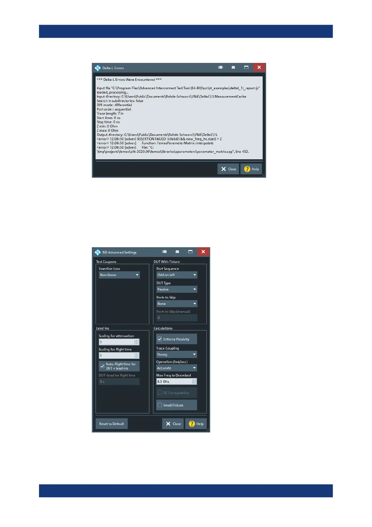
Figure 5-64: Delta-L error messages
5.13.5.6
ISD Advanced Settings
Advanced settings of the ISD tool. For details, see the ISD User Guide.
For the analyzer firmware, these settings are global.
Offset Embed softtool
634
636
Table of Contents
Cover
1
Contents
3
1 Safety and regulatory information
15
1.1 Safety instructions
15
1.2 Warning messages in the documentation
18
1.3 Korea certification class A
18
2 Welcome to the R&S ZNB/ZNBT
19
2.1 What's new in firmware version 3.45
19
2.2 Documentation overview
20
2.2.1 Getting started manual
21
2.2.2 User manual and help
21
2.2.3 Service manual
21
2.2.4 Instrument security procedures
21
2.2.5 Printed safety instructions
21
2.2.6 Data sheets and brochures
22
2.2.7 Release notes and open source acknowledgment (OSA)
22
2.2.8 Application notes, application cards, white papers, etc.
22
3 Getting started
23
3.1 Preparing for use
23
3.1.1 Lifting and carrying
23
3.1.2 Unpacking and checking
23
3.1.3 Choosing the operating site
23
3.1.4 Setting up the product
24
3.1.4.1 Placing the product on a bench top
24
3.1.4.2 Mounting the product in a rack
25
3.1.5 Considerations for test setup
26
3.1.6 Connecting the analyzer to the AC supply
27
3.1.7 Switching the instrument on and off
28
3.1.8 Standby and ready state
29
3.1.9 Windows operating system
29
3.1.10 Minimizing the VNA application
31
3.1.11 Connecting external accessories
31
3.1.11.1 Connecting a monitor
32
3.1.11.2 Connecting a keyboard
33
3.1.11.3 Connecting a mouse
33
3.1.11.4 Connecting a printer
33
3.1.11.5 Connecting a LAN cable
34
3.1.11.6 Connecting a USB cable for remote control
34
3.1.12 Remote operation in a LAN
35
3.1.12.1 Assigning an IP address
35
3.1.12.2 Using computer names
37
3.1.12.3 Remote Desktop connection
37
3.1.12.4 Windows® firewall settings
38
3.2 Instrument tour
39
3.2.1 Front panel R&S ZNB
39
3.2.1.1 Touchscreen
40
3.2.1.2 Function keys
40
3.2.1.3 Data entry keys
41
3.2.1.4 Rotary knob
42
3.2.1.5 Navigation keys
42
3.2.1.6 Standby key
43
3.2.1.7 Front panel connectors
43
Test ports
43
USB connectors
44
3.2.2 Front panel R&S ZNBT
44
3.2.2.1 Test ports
45
3.2.2.2 Administrative area
46
3.2.3 Rear panel R&S ZNB
47
3.2.4 Rear panel R&S ZNBT
49
3.3 Operating the instrument
51
3.3.1 Manual operation
52
3.3.2 Control elements of the application window
56
3.3.2.1 Title bar
57
3.3.2.2 Toolbar
57
3.3.2.3 Softtools
58
3.3.2.4 Menu bar
59
3.3.2.5 Menu structure
59
3.3.2.6 Hardkey panel
60
3.3.2.7 Status bar
61
3.3.3 Touchscreen gestures
62
3.3.4 Working with dialogs
64
3.3.5 Handling diagrams, traces, and markers
66
3.3.5.1 Adding new traces and diagrams
66
3.3.5.2 Adding new markers
67
3.3.5.3 Deleting display elements
68
3.3.5.4 Using drag and drop
69
3.3.6 Entering data
69
3.3.6.1 Using front panel keys
70
3.3.6.2 Using the numeric editor
71
3.3.6.3 Using the analyzer's on-screen keyboard
71
3.3.6.4 Using the Windows® on-screen keyboard
72
3.3.7 Scaling diagrams
73
3.3.7.1 Using the graphical zoom
73
3.3.7.2 Setting the sweep range
74
3.3.7.3 Reference value and position
75
3.3.7.4 Auto scale
75
3.3.7.5 Circular diagrams
76
3.3.7.6 Set by marker
76
3.3.7.7 Enlarging a diagram
77
3.4 Performing measurements
78
3.4.1 Transmission S-parameter measurement
78
3.4.1.1 Connecting the instrument for transmission measurements
78
3.4.1.2 Selecting the sweep range and other parameters
80
3.4.1.3 Calibrating the instrument
81
3.4.1.4 Evaluating data
83
3.4.1.5 Saving and printing data
84
3.4.2 Reflection S-parameter measurement
85
4 Concepts and features
87
4.1 Basic concepts
87
4.1.1 Global (persistent) settings
87
4.1.2 Recall sets
88
4.1.3 Traces, channels and diagrams
88
4.1.3.1 Trace settings
89
4.1.3.2 Channel settings
89
4.1.3.3 Active and inactive traces and channels
90
4.1.4 Sweep control
90
4.1.4.1 Partial measurements and driving mode
91
4.1.4.2 Pipelining of measurement data
92
4.1.4.3 Parallel measurements on multiple DUTs
94
4.1.4.4 Stimulus and sweep types
96
4.1.4.5 Stepped vs. swept mode
97
4.1.5 Data flow
98
4.1.5.1 Channel data flow
98
4.1.5.2 Trace data flow
100
4.2 Screen elements
102
4.2.1 Display elements of a diagram
102
4.2.1.1 Title
103
4.2.1.2 Traces
103
Trace types
103
Trace list and trace settings
104
4.2.1.3 Markers
105
Activating and moving markers
106
Marker info field
106
Marker format
107
Marker coupling
109
Basic marker search functions
110
Multiple peak search
110
Bandfilter search
110
4.2.1.4 Channel list and channel settings
112
4.2.1.5 Context menus
113
4.2.2 Dialogs
113
4.2.2.1 Immediate vs. confirmed settings
114
4.2.2.2 Common dialogs
115
4.2.2.3 Multi-channel setup dialog
116
4.2.3 Trace formats
117
4.2.3.1 Cartesian trace formats
117
Diagram representation
117
Conversion of complex to real quantities
118
4.2.3.2 Complex trace formats
118
Polar
119
Smith
120
Inv Smith
122
4.2.3.3 Measured quantities and trace formats
124
4.3 Measurement results
125
4.3.1 S-parameters
125
4.3.1.1 Multiport S-parameters
127
4.3.1.2 Redefined S-parameters
127
4.3.2 Reference impedances
128
4.3.3 Impedance parameters
130
4.3.3.1 Converted impedances
130
Reflection impedance
131
Series transmission impedance
131
Parallel transmission impedance
132
Shunt-thru measurements
132
4.3.3.2 Z-parameters
133
2-port Z-parameters
133
4.3.4 Admittance parameters
134
4.3.4.1 Converted admittances
134
4.3.4.2 Y-parameters
134
2-port Y-parameters
134
4.3.5 Wave quantities and ratios
135
4.3.5.1 Wave quantities
135
4.3.5.2 Ratios
136
4.3.5.3 Detector settings
136
4.3.6 Unbalance-balance conversion
138
4.3.6.1 Balanced port configurations
138
4.3.6.2 Mixed-mode parameters
139
Mixed-mode parameters for different test setups
140
4.3.6.3 Imbalance and common mode rejection
141
4.3.7 Stability factors
142
4.3.8 Group delay
143
4.4 Operations on traces
144
4.4.1 Limit check
144
4.4.1.1 Rules for limit line definition
145
4.4.1.2 Rules for ripple test definition
147
4.4.1.3 Circle limits
148
4.4.1.4 File format for limit lines
150
4.4.1.5 File format for ripple limits
151
4.4.2 Trace files
151
4.4.2.1 Touchstone files
152
General syntax rules
152
Option line
152
Comments
153
Keywords (version 2.0 only)
155
Network parameter data
157
Conditions for Touchstone file export
158
Renormalization of S-parameters
159
4.4.2.2 ASCII (*.csv) files
159
4.4.2.3 Finding the best file format
160
4.4.3 Memory-mapped trace data transfer
160
4.5 Calibration
162
4.5.1 Calibration types
163
4.5.1.1 Normalization (reflection, transmission)
166
4.5.1.2 Reflection OSM calibration
166
4.5.1.3 One Path Two Ports Calibration
166
4.5.1.4 TOSM and UOSM calibration
167
4.5.1.5 Adapter removal
168
4.5.1.6 TOM calibration
170
4.5.1.7 TSM calibration
170
4.5.1.8 TRM calibration
170
4.5.1.9 TRL calibration
170
4.5.1.10 TNA calibration
173
4.5.1.11 Full n-Port calibration with reduced number of Through connections
173
4.5.1.12 Complementary isolation measurement
174
4.5.2 Calibration standards and calibration kits
174
4.5.2.1 Calibration standard types
175
4.5.2.2 Cal kit parameter types
177
4.5.2.3 Sliding Match standards
178
4.5.2.4 Cal kit Files
179
4.5.3 Calibration pool
181
4.5.4 Calibration labels
181
4.5.5 Automatic calibration
181
4.5.5.1 Connecting the calibration unit
182
4.5.5.2 Performing an automatic calibration
183
4.5.5.3 Characterization of calibration units
185
4.5.5.4 Inline calibration
186
4.5.5.5 Calibration validation
189
4.5.5.6 Multiple port assignments
191
4.5.6 Scalar power calibration
193
4.5.6.1 Source power calibration
195
4.5.6.2 Measurement receiver calibration
196
4.5.6.3 Power calibration labels
197
4.5.6.4 Extended test setups
198
4.5.7 SMARTerCal
199
4.5.7.1 Calibration procedure
200
4.5.7.2 Calibration types
200
4.5.7.3 Combining SMARTerCal with scalar power calibration
200
4.5.7.4 Calibration labels
201
4.5.8 Parallel calibration of multiple channels
201
4.5.9 Joining calibrations
202
4.6 Offset parameters and de-/embedding
202
4.6.1 Offset parameters
202
4.6.1.1 Definition of offset parameters
203
4.6.1.2 Definition of loss parameters
203
4.6.1.3 Auto Length
204
4.6.1.4 Auto Length and Loss
205
4.6.1.5 Fixture Compensation
206
4.6.1.6 Application and effect of offset parameters
207
4.6.1.7 Offset parameters for balanced ports
208
4.6.2 Embedding and deembedding
208
4.6.2.1 Embedding a DUT
209
4.6.2.2 Deembedding a DUT
210
4.6.2.3 Circuit models for 2-port networks
210
4.6.2.4 Circuit models for 4-port networks
212
4.6.2.5 Port pair de-/embedding
213
4.6.2.6 Port set de-/embedding
214
4.6.2.7 Ground loop de-/embedding
216
4.6.2.8 Differential match embedding
216
4.6.2.9 Fixture modeling and deembedding
217
4.6.2.10 Combining Several de-/embedding networks
219
4.7 Optional extensions and accessories
221
4.7.1 Additional test ports (R&S ZNBT only)
222
4.7.2 Time domain analysis
222
4.7.2.1 Chirp z-transformation
223
4.7.2.2 Band pass and low pass mode
223
4.7.2.3 Windows in the frequency domain
225
4.7.2.4 Harmonic grid
225
4.7.2.5 Time gates
227
Time-gated frequency domain trace
228
4.7.2.6 Time domain SVSWR measurements
228
4.7.2.7 Extended time domain analysis
230
4.7.3 Distance-to-fault measurements
235
4.7.4 Frequency conversion measurements
236
4.7.4.1 Calibration options
238
4.7.4.2 Scalar mixer measurements
238
Two-stage mixer measurements
239
Mixer diagrams
239
4.7.4.3 Intermodulation measurements
241
Intermodulation measurement results
244
Intermodulation quantities
246
4.7.5 Receiver bandwidth 10 MHz
246
4.7.6 Frequency resolution 1 mHz
247
4.7.7 Measurement uncertainty analysis
247
4.7.8 Eazy de-embedding based on IEEE 370
250
4.7.9 In-situ de-embedding
251
4.7.10 Smart fixture de-embedding
252
4.7.11 Delta-L 4.0 PCB characterization
252
4.7.12 Health and usage monitoring service (HUMS)
253
4.7.13 Bias tees (R&S ZNB only)
254
4.7.14 Internal second source
255
4.7.15 Precision frequency reference
255
4.7.16 GPIB interface
256
4.7.17 Device control
256
4.7.18 Handler I/O (universal interface)
256
4.7.19 RFFE GPIO interface
257
4.7.20 Additional removable system drive
258
4.7.21 Extended power range
258
4.7.22 Extended dynamic range
259
4.7.23 Receiver step attenuators
261
4.7.24 R&S ZNB40 reflector module with ESD limiters
262
4.7.25 DC inputs
262
4.7.25.1 Power added efficiency
262
4.7.26 USB-to-IEC/IEEE adapter
265
4.7.27 External power meters
265
4.7.27.1 Zeroing
266
4.7.28 External generators
267
4.7.29 External switch matrices
269
4.7.29.1 Overview
269
4.7.29.2 Matrix setup and operation
271
4.7.29.3 RF connections and matrix connectivity
271
4.7.29.4 Multiple paths: precision vs. speed
273
4.7.29.5 Multiple paths and calibration
275
4.7.30 External DLLs
276
4.7.30.1 Basic use case
277
4.7.30.2 Technology
277
4.7.30.3 Trace calculation in the channel calculation chain
278
4.7.31 R&S ZNXSIM
278
4.7.31.1 Simulation data
279
4.7.31.2 Simulation noise
280
5 GUI reference
282
5.1 Function Keys and Softtools
282
5.2 Meas softtool
284
5.2.1 S-Params tab
285
5.2.1.1 Controls on the S-Params tab
285
5.2.1.2 S-Parameter Wizard
287
5.2.1.3 Balanced Ports dialog
289
Predefined Config tab
289
Logical Port Config tab
290
User Config tab
291
Reference Impedance tab
292
5.2.2 Ratios tab
294
5.2.2.1 Controls on the Ratios tab
294
5.2.2.2 More Ratios dialog
295
5.2.3 Wave tab
297
5.2.3.1 Controls on the Wave tab
297
5.2.3.2 More Wave Quantities dialog
298
5.2.4 Intermod. tab
300
5.2.4.1 Controls on the Intermod. tab
301
5.2.4.2 IM Products dialog
302
5.2.4.3 Intercept Points dialog
303
5.2.5 Z←Sij tab
304
5.2.6 Y←Sij tab
306
5.2.7 Y-Z-Params tab
308
5.2.8 Imbal. CMRR tab
309
5.2.8.1 Controls on the Imbal. CMRR tab
310
5.2.8.2 Imbalance Differential dialog
311
5.2.9 Stability tab
312
5.2.10 Power Sensor tab
313
5.2.11 DC tab
314
5.2.11.1 Controls on the DC tab
315
5.2.11.2 Power Added Efficiency (PAE) dialog
315
5.2.12 External DLL tab
317
5.2.12.1 Controls on the External DLL tab
318
5.2.12.2 External DLL Configuration Dialog
318
5.2.12.3 Trace Definition Dialog
320
5.3 Format softtool
322
5.4 Scale softtool
328
5.4.1 Scale Values tab
328
5.4.2 Scale Coupling tab
330
5.4.3 Zoom tab
331
5.5 Trace Config softtool
333
5.5.1 Traces tab
333
5.5.1.1 Controls on the Traces tab
334
5.5.1.2 New Trace dialog
336
5.5.1.3 Trace Manager dialog
336
5.5.2 Mem tab
338
5.5.3 All Mem All Data tab
341
5.5.4 Math tab
342
5.5.4.1 Controls on the Math tab
343
5.5.4.2 User Def Math dialog
344
5.5.5 Time Domain tab
348
5.5.5.1 Controls on the Time Domain tab
348
5.5.5.2 Low Pass Settings dialog
351
5.5.6 Time Gate tab
353
5.5.7 Distance to Fault tab
355
5.5.8 Trace Statistics tab
355
5.5.8.1 Controls on the Trace Statistics tab
355
5.5.8.2 Evaluation Range dialog
360
5.5.9 Smooth Shift Hold tab
361
5.5.10 Infinite Averaging tab
364
5.5.11 Trace Data tab
365
5.5.11.1 Import Complex Data dialog
366
5.5.11.2 Export Data - <File Type> dialog
367
5.5.11.3 Select Parameter dialog
371
5.5.11.4 Select Ports dialog
371
5.6 Lines softtool
373
5.6.1 Limit Test tab
373
5.6.1.1 Controls on the Limit Test tab
374
5.6.1.2 Define Limit Lines dialog
377
Controls on the Define Limit Lines dialog
378
Response dialog
381
5.6.2 Ripple Test tab
381
5.6.2.1 Controls on the Ripple Test tab
382
5.6.2.2 Define Ripple Test dialog
384
5.6.3 Circle Test tab
386
5.6.4 Display Circle tab
389
5.6.5 Horiz. Line tab
390
5.7 Marker softtool
391
5.7.1 Markers tab
391
5.7.2 Marker Props tab
394
5.7.3 Marker Search tab
396
5.7.3.1 Controls on the Marker Search tab
397
5.7.3.2 Search Range dialog
399
5.7.3.3 Marker Config dialog
400
5.7.4 Multiple Peak tab
402
5.7.4.1 Controls on the Multiple Peak tab
402
5.7.4.2 Multiple Marker Config dialog
403
5.7.5 Target Search tab
404
5.7.6 Bandfilter tab
406
5.7.7 Set by Marker tab
410
5.7.8 Info Field tab
412
5.7.9 Marker Coupling tab
412
5.8 Stimulus softtool
413
5.8.1 Stimulus tab
414
5.8.2 Power tab
415
5.8.2.1 Controls on the Power tab
416
5.8.3 Time Domain X-Axis tab
418
5.9 Power Bw Avg softtool
419
5.9.1 Power tab
419
5.9.2 Bandwidth tab
420
5.9.3 Average tab
421
5.10 Sweep Softtool
422
5.10.1 Sweep Params tab
423
5.10.2 Sweep Type tab
426
5.10.2.1 Controls on the Sweep Type tab
426
5.10.2.2 Define Segments dialog
431
Controls in the Define Segments dialog
432
Displayed Columns dialog
434
5.10.3 Trigger tab
437
5.10.3.1 Controls on the Trigger tab
437
5.10.3.2 Trigger Manager dialog
440
5.10.4 Sweep Control tab
441
5.10.4.1 Controls on the Sweep Control tab
442
5.10.4.2 Restart Manager dialog
444
5.11 Cal softtool
445
5.11.1 Start Cal tab
446
5.11.1.1 Controls on the Start Cal tab
446
5.11.1.2 Channel Selection for Calibration dialog
447
5.11.1.3 Calibration Unit wizard
448
Step 1: Ports
449
Step 2: Connections
453
Step 3: Cal Unit
455
5.11.1.4 Calibration Unit wizard (MultiCal)
458
Step 1: Ports
459
Define Calibration dialog
459
Step 2: Connections
462
Step 3: Cal Unit
463
5.11.1.5 Calibration Setting wizard
463
Step 1: Ports and Type
463
Step 2: Connectors and Cal Kits
465
Step 3: Calibration
468
5.11.1.6 Calibration Setting wizard (MultiCal)
472
Step 1: Ports and Type
472
Define Calibration dialog
473
Step 2: Connectors and Cal Kits
475
Step 3: Calibration
476
5.11.1.7 Power Cal wizard
476
Screen elements
477
Power Cal dialog – Ref. Receiver
479
Power Cal dialog – Meas. Receiver
480
Power Cal dialog – Source Flatness
481
5.11.1.8 SMARTerCal wizard (Cal Unit)
482
Step 1: Ports
483
Step 2: Connections
487
Step 3: SMARTerCal
488
5.11.1.9 SMARTerCal wizard (Cal Unit, MultiCal)
491
Step 1: Ports
492
Define Calibration Dialog
493
Step 2: Connections
495
Step 3: SMARTerCal
496
5.11.1.10 SMARTerCal wizard (manual)
496
Step 1: Ports and Type
497
Step 2: Connectors and Cal Kits
500
Step 3: SMARTerCal
502
5.11.1.11 SMARTerCal wizard (manual, MultiCal)
505
Step 1: Ports and Type
506
Define Calibration dialog
506
Step 2: Connectors and Cal Kits
508
Step 3: Calibration
509
5.11.1.12 Cal Validation dock widget
509
Basic mode
509
Advanced mode
510
5.11.2 Cal Devices tab
511
5.11.2.1 Cal Connector Types dialog
512
5.11.2.2 Calibration Kits dialog
514
Controls in the Calibration Kits dialog
515
Kit Standards dialog
516
View / Modify Cal Kit Standards dialog
518
5.11.2.3 Characterize Cal Unit dialog
519
Controls in the Characterize Cal Unit dialog
520
Characterization wizard
521
Step 1: Characterization
521
Step 2: Save Characterization Data
523
5.11.3 Pwr Cal Settings tab
524
5.11.3.1 Controls on the Pwr Cal Settings tab
525
5.11.3.2 Modify Cal Power dialog
527
5.11.3.3 Power Meter Transmission Coefficients dialog
529
Controls in the Power Meter Transmission Coefficients dialog
530
Two Port Configuration dialog
530
5.11.4 Use Cal tab
531
5.11.4.1 Controls on the Use Cal tab
532
5.11.4.2 Active Power Cals dialog
533
5.11.4.3 Calibration Manager dialog
534
5.11.4.4 JoinCal dialog
537
5.11.5 METAS Cal tab
538
5.11.5.1 Controls on the METAS Cal tab (option K50)
538
5.11.5.2 METAS Calibration (Manual) dialog
540
Step 1: Ports and Type
540
Step 2: Connectors and Cal Kits
541
Step 3: Calibration
543
5.11.5.3 METAS Verification dialog
543
Step 1: Verification Kit
543
Step 2: METAS Verification
545
5.11.5.4 METAS Reconnection dialog
546
5.12 Channel Config softtool
547
5.12.1 Channels tab
547
5.12.1.1 Controls on the Channels tab
547
5.12.1.2 Channel Manager dialog
550
5.12.1.3 RFFE Config dialog for R&S ZN-B15/-Z15 Var. 03
551
RFFE tab
551
Sweep Sequencer tab
552
GPIOs tab
552
5.12.1.4 RFFE interface configuration
553
Basic RFFE interface settings and command execution
553
RFFE interface voltage and current measurements
554
5.12.1.5 GPIO configuration
556
Basic GPIO configuration
556
GPIO voltage and current measurements
557
5.12.1.6 Sweep Sequencer
558
5.12.2 Port Config tab
560
5.12.2.1 Controls on the Port Config tab
561
5.12.2.2 Port Settings dialog
562
Arb Frequency tab
562
Modify Frequency Conversion dialog
565
Arbitrary Power tab
566
Modify Cal Power dialog
567
Receiver Level tab
568
Common controls
569
Stimulus dialog
569
5.12.2.3 Define Parallel Measurement dialog
570
DUT Definition tab
572
Balanced Ports tab
574
Reference Impedance tab
575
Frequency Offset tab
575
5.12.3 Mode tab
577
5.12.3.1 Controls on the Mode tab
577
5.12.3.2 AGC Manual Configuration dialog
580
5.12.4 Intermod. tab
582
5.12.4.1 Controls on the Intermod tab
582
5.12.4.2 Intermodulation Presetting wizard
584
5.12.4.3 Define Intermodulation Distortion Measurement dialog
588
5.12.4.4 Frequencies and Power dialog
591
5.12.4.5 Intermod. Pwr. Cal wizard
592
5.12.5 Pwr Cal Settings tab
594
5.12.6 Mixer Mode tab
594
5.12.6.1 Controls on the Mixer Mode tab
595
5.12.6.2 Mixer Presetting wizard
595
5.12.6.3 (Mixer) Setup dialog
598
5.12.6.4 SMARTerCal (Cal Unit) wizard for mixer mode
602
5.12.6.5 SMARTerCal (Manual) wizard for mixer mode
603
5.13 Offset Embed softtool
605
5.13.1 Offset Embed dock widget
605
5.13.1.1 Overview panel
605
5.13.1.2 Offset panel
606
5.13.1.3 Single Ended panel
608
5.13.1.4 Port Sets panel
609
5.13.1.5 Balanced panel
611
5.13.1.6 Ground Loop panel
612
5.13.1.7 Impedance Renormalization panel
613
5.13.1.8 Differential Match panel
614
5.13.2 Offset tab
615
5.13.2.1 Controls on the Offset tab
616
5.13.2.2 Fixture Compensation dialog
619
5.13.3 One Way Loss tab
621
5.13.4 Single Ended tab
623
5.13.5 Fixture modeling dialog
626
5.13.5.1 Common controls on the dialog
628
5.13.5.2 Measure Coupon
629
5.13.5.3 Measure DUT + Test Fixture
631
5.13.5.4 Save Fixture Model
632
5.13.5.5 <Deembedding Tool> Errors dialog
634
5.13.5.6 ISD Advanced Settings
635
5.13.5.7 SFD Advanced Settings
638
5.13.5.8 EZD Advanced Settings
639
5.13.6 Port Sets tab
641
5.13.7 Balanced tab
643
5.13.8 Ground Loop tab
646
5.13.9 Differential Match tab
649
5.13.10 Config tab
650
5.13.11 Deembed Assistant tab
652
5.13.11.1 Controls on the Deembed Assistant tab
652
5.13.11.2 Deembedding Assistant dock widget panel
654
Page 1: Topology
654
Page 2: Measure / Load and Apply
658
5.13.12 Delta-L tab
661
5.13.12.1 Delta-L Settings dialog
662
5.13.12.2 Delta-L measurement
664
Delta-L Measurement dock widget
664
Delta-L diagram
666
5.14 File softtool
668
5.14.1 Recall sets tab
669
5.14.1.1 Basic Recall Set functions
669
5.14.1.2 Restore Switch Matrix Configuration dialog
671
5.14.2 Favorites tab
673
5.14.3 Print tab
674
5.14.4 Printer Setup dialog
675
5.14.4.1 Content tab
675
5.14.4.2 Printer tab
676
5.14.4.3 Page Setup tab
676
5.14.5 Trace Data tab
676
5.14.6 More tab
677
5.14.7 Configure Additional Simulation Data dialog
678
5.14.7.1 Configure Additional Imports tab
678
5.14.7.2 Resulting S Matrix Overview tab
680
5.15 DUT Softtool
681
5.16 Applic softtool
681
5.16.1 External Tools application
682
5.16.2 TDR application
683
5.16.2.1 TDR Setup tab
683
5.16.2.2 TDR Wizard
684
Step 1: Port Topology
685
Step 2: Stimulus Settings
686
5.16.2.3 TDR Stimulus Settings dialog
687
Controls in the TDR Stimulus Settings dialog
687
TDR Stimulus - Advanced Settings dialog
688
5.16.2.4 Eye Diag tab
689
5.16.2.5 Eye Diagram dialog
692
5.16.2.6 Advanced Settings dialog
695
Controls in the dialog
695
Generator
696
Emphasis
697
Jitter
698
Noise
700
DUT
701
Equalization
702
5.16.2.7 Eye Mask Test tab
703
5.16.2.8 Define Mask Configuration dialog
704
5.16.2.9 Rise Time tab
707
5.16.2.10 Skew tab
708
5.16.2.11 Time Gate tab
710
5.16.2.12 Y Axis tab
710
5.16.2.13 X Axis tab
711
5.16.3 DUT Centric application
711
5.16.3.1 DUT Centric Wizard
712
Guided mixer setup
713
Define DUT
713
DUT/VNA connections
714
Measurement Selection
715
Channel Settings
716
Summary
717
Guided amplifier setup
718
Define DUT
718
DUT/VNA connections
719
Measurement Selection
720
Channel Settings
721
Summary
721
Guided Calibration wizard
722
Step 1: channel selection
722
Step 2: calibration settings
723
Step 3: ports and calibration types
723
5.16.3.2 DUT Manager dialog
724
Controls on the DUT Manager dialog
724
Amplifier Configuration dialog
725
Mixer Configuration dialog
726
5.16.4 Distance to Fault Application
727
5.16.4.1 Controls on the Distance to Fault tab
727
5.16.4.2 Available Cable Types... dialog
732
5.16.4.3 Fault List dock widget
734
5.17 Display softtool
735
5.17.1 Diagram tab
735
5.17.2 Split tab
739
5.17.3 Config tab
741
5.17.3.1 Controls on the Config tab
741
5.17.3.2 Define User Color Scheme dialog
743
5.17.3.3 Info Window
746
Info Window Configuration dialog
747
5.17.4 View Bar tab
748
5.17.5 Touchscreen tab
749
5.18 Setup softtool
750
5.18.1 Setup tab
750
5.18.1.1 Controls on the Setup tab
750
5.18.1.2 System Config dialog
751
Presets tab
752
Calibration tab
753
User Interface tab
755
Messages tab
757
Channel Bits tab
758
Advanced tab
759
Power tab
761
Recovery tab
763
HUMS tab
763
Common controls
764
Protocol subtab
764
Device Tags subtab
765
5.18.1.3 Info dialog
766
Common controls in the Info dialog
766
Setup tab
767
Options tab
768
Hardware tab
768
Selftest tab
769
Error Log tab
769
Cal Validation tab
769
Service tab
770
5.18.1.4 Operators Check wizard
771
Welcome page
771
Selftest page
772
Power Check page
772
Summary page
774
5.18.1.5 Service Function dialog
775
5.18.2 Freq. Ref. tab
776
5.18.3 Remote Settings tab
777
5.18.3.1 Controls on the Remote Settings tab
777
5.18.4 External Devices tab
779
5.18.4.1 Controls on the External Devices tab
780
5.18.4.2 External Power Meters dialog
780
5.18.4.3 External Power Meter Config dialog
784
5.18.4.4 External Generators dialog
785
5.18.4.5 Inline Calibration Systems dialog
789
5.18.5 External Ports tab
790
5.18.5.1 Controls on the External Ports tab
790
5.18.5.2 Define Physical Ports dialog
791
5.18.5.3 External Matrices dialog
791
5.18.5.4 Device LAN Configuration dialog
795
5.18.5.5 Switch Matrix RF Connections dialog
796
5.19 Help softtool
800
5.20 Additional Function Keys
801
6 Remote control
803
6.1 Introduction to remote control
803
6.1.1 Remote control via USB
804
6.1.2 Starting a remote control session
805
6.1.3 GPIB Explorer
805
6.1.4 Switchover to remote control
807
6.1.4.1 Setting the device address
809
6.1.4.2 Returning to manual operation
810
6.1.5 Combining manual and remote control
810
6.2 Messages
811
6.2.1 Device messages (commands and device responses)
811
6.2.2 SCPI command structure and syntax
811
6.2.2.1 Common commands
812
6.2.2.2 Instrument-control commands
812
6.2.2.3 Structure of a command line
813
6.2.2.4 Responses to queries
814
6.2.3 SCPI parameters
815
6.2.3.1 Numeric values
815
6.2.3.2 Boolean parameters
816
6.2.3.3 Text parameters
816
6.2.3.4 Strings
816
6.2.3.5 Block data format
816
6.2.3.6 Overview of syntax elements
817
6.3 Basic remote control concepts
817
6.3.1 Traces, channels, and diagram areas
817
6.3.2 Active traces in remote control
818
6.3.3 Initiating measurements, speed considerations
819
6.3.4 Addressing traces and channels
820
6.4 Command processing
821
6.4.1 Input unit
821
6.4.2 Command recognition
822
6.4.3 Data base and instrument hardware
822
6.4.4 Status reporting system
823
6.4.5 Output unit
823
6.4.6 Command sequence and command synchronization
823
6.5 Status reporting system
825
6.5.1 Overview of status registers
826
6.5.2 Structure of a SCPI status register
827
6.5.3 Contents of the status registers
829
6.5.3.1 STB and SRE
830
6.5.3.2 IST flag and PPE
831
6.5.3.3 ESR and ESE
831
6.5.3.4 STATus:OPERation
832
6.5.3.5 STATus:QUEStionable
832
STATus:QUEStionable:LIMit<1|2>
832
STATus:QUEStionable:INTegrity...
833
6.5.4 Application of the status reporting system
836
6.5.4.1 Service request
836
6.5.4.2 Serial poll
837
6.5.4.3 Parallel poll
837
6.5.4.4 Query of an instrument status
838
6.5.4.5 Error queue
838
6.5.5 Reset values of the status reporting system
839
7 Command reference
840
7.1 Special terms and notation
840
7.1.1 Upper- vs. lower-case
841
7.1.2 Special characters
841
7.1.3 Parameters
841
7.1.4 Numeric suffixes
841
7.2 Common commands
842
7.3 SCPI command reference
843
7.3.1 CALCulate commands
844
7.3.1.1 CALCulate:CALValidate...
844
7.3.1.2 CALCulate:DATA...
846
7.3.1.3 CALCulate:DTIMe...
855
7.3.1.4 CALCulate:EYE...
858
7.3.1.5 CALCulate:FILTer[:GATE]...
882
7.3.1.6 CALCulate:FMODel...
887
CALCulate:FMODel:DEASsistant...
887
CALCulate:FMODel:DELT...
893
CALCulate:FMODel:EZD...
902
CALCulate:FMODel:ISD...
908
CALCulate:FMODel:SFD...
917
CALCulate:FMODel... (other)
921
7.3.1.7 CALCulate:LIMit...
922
7.3.1.8 CALCulate:MARKer...
940
7.3.1.9 CALCulate:MATH...
963
7.3.1.10 CALCulate:PARameter...
967
7.3.1.11 CALCulate:RIPPle...
976
7.3.1.12 CALCulate:STATistics...
985
7.3.1.13 CALCulate:TRANsform...
994
CALCulate:TRANsform:DTFault...
994
CALCulate:TRANsform:TIME...
1000
CALCulate:TRANsform:VNETworks...
1007
CALCulate:TRANsform... (other)
1056
7.3.1.14 CALCulate:TTIMe:...
1057
7.3.1.15 CALCulate... (other)
1059
7.3.2 CONFigure commands
1065
7.3.3 CONTrol commands
1074
7.3.4 DIAGnostic commands
1097
7.3.5 DISPlay commands
1099
7.3.6 FORMat commands
1125
7.3.7 HCOPy commands
1126
7.3.8 INITiate commands
1132
7.3.9 INSTrument commands
1135
7.3.10 MEMory commands
1136
7.3.11 MMEMory commands
1138
7.3.12 OUTPut commands
1178
7.3.13 PROGram commands
1183
7.3.14 [SENSe:] commands
1186
7.3.14.1 [SENSe:]AVERage...
1186
7.3.14.2 [SENSe:]BANDwidth...
1188
7.3.14.3 [SENSe:]CDLL...
1189
7.3.14.4 [SENSe:]CORRection:CKIT...
1193
7.3.14.5 [SENSe:]CORRection:CKIT... with Labels
1201
7.3.14.6 [SENSe:]CORRection:COLLect...
1206
7.3.14.7 [SENSe:]CORRection:METas
1242
7.3.14.8 [SENSe:]CORRection... (other)
1245
7.3.14.9 [SENSe:]FREQuency...
1267
7.3.14.10 [SENSe:]HARMonic...
1285
7.3.14.11 [SENSe:]LPORt...
1288
7.3.14.12 [SENSe:]PAE...
1289
7.3.14.13 [SENSe:]POWer...
1292
7.3.14.14 [SENSe:]ROSCillator...
1297
7.3.14.15 [SENSe:]SEGMent...
1298
7.3.14.16 [SENSe:]SWEep...
1319
7.3.14.17 [SENSe:]... (other)
1329
7.3.15 SOURce commands
1331
7.3.15.1 SOURce:FREQuency...
1332
7.3.15.2 SOURce:GROup...
1337
7.3.15.3 SOURce:POWer:CORRection:COLLect...
1348
7.3.15.4 SOURce:POWer:CORRection:TCOefficient...
1351
7.3.15.5 SOURce:POWer:CORRection... (other)
1358
7.3.15.6 SOURce:POWer... (other)
1368
7.3.15.7 SOURce... (other)
1378
7.3.16 STATus commands
1380
7.3.17 SYSTem commands
1383
7.3.17.1 SYSTem:COMMunicate...
1383
7.3.17.2 SYSTem:DATA:MEMory...
1408
7.3.17.3 SYSTem:... (other)
1410
7.3.18 TRACe commands
1429
7.3.19 TRIGger commands
1432
7.3.19.1 TRIGger[:SEQuence]...
1432
7.3.19.2 TRIGger:CHANnel:AUXiliary...
1436
7.4 HUMS and service date commands
1439
7.4.1 SNMP/REST commands
1439
7.4.2 System information commands
1443
7.4.3 Device tags commands
1453
7.4.4 Utilization commands
1454
7.4.5 Service date commands
1461
7.5 R&S ZVR/ZVABT compatible commands
1463
8 Programming examples
1490
8.1 Basic tasks
1490
8.1.1 Typical stages of a remote control program
1490
8.1.1.1 Basic instrument settings
1490
8.1.1.2 Adjusting the test setup
1491
8.1.1.3 Start of the measurement and command synchronization
1491
8.1.1.4 Retrieving measurement results
1493
8.1.2 Channel, trace and diagram handling
1493
8.1.2.1 Several traces with equal channel settings
1493
8.1.2.2 Several traces with different channel settings...
1495
8.1.2.3 Markers and limit lines...
1497
8.2 Condensed programming examples
1499
8.2.1 Path-independent remote control programs
1500
8.2.2 Trace and diagram handling
1500
8.2.2.1 Assigning channels, traces, and diagrams
1500
8.2.2.2 Memory traces
1502
8.2.2.3 Trace mathematics
1503
8.2.2.4 Trace statistics
1505
8.2.2.5 Bandfilter search
1506
8.2.2.6 Creating diagrams
1507
8.2.3 Using markers
1509
8.2.3.1 Marker search functions
1510
8.2.4 Data handling
1511
8.2.4.1 Single sweep mode
1511
8.2.4.2 Modeling a max hold function
1512
8.2.4.3 Retrieving the results of previous sweeps
1513
8.2.4.4 Exporting S-parameters
1515
8.2.5 Calibration
1515
8.2.5.1 One and two-port calibration
1515
8.2.5.2 MultiCal (with calibration unit)
1516
8.2.5.3 Saving and recalling error terms
1518
Performing a calibration, saving the error terms
1518
Performing a new calibration, recalling the error terms
1519
Using calibration data recorded previously
1520
8.2.5.4 Adapter removal
1521
8.2.5.5 Inline calibration
1521
8.2.6 Mixer measurement
1522
8.2.7 RFFE/GPIO interface programming
1524
8.2.8 Fixture modeling
1527
9 Error messages and troubleshooting
1528
9.1 Errors during firmware operation
1528
9.1.1 Asynchronous errors
1529
9.1.2 Errors during measurement
1529
9.2 Errors during firmware installation/update
1530
9.3 Collecting information for technical support
1532
9.4 Contacting customer support
1533
10 Transporting
1534
11 Maintenance, storage and disposal
1535
11.1 Replacing fuses
1535
11.2 Cleaning
1535
11.3 Storage
1536
11.3.1 Disposal
1536
12 Annexes
1537
12.1 Firmware installation
1537
12.2 System recovery
1538
12.3 Interfaces and connectors
1538
12.3.1 Rear panel connectors
1538
12.3.1.1 User Port
1538
12.3.1.2 Trigger In
1540
12.3.1.3 Trigger Out
1540
12.3.2 LAN interface
1540
12.3.2.1 VXI-11 interface messages
1540
12.3.3 GPIB interface
1541
12.3.3.1 Interface functions
1542
12.3.3.2 Interface messages
1542
12.3.3.3 Instrument messages
1543
12.3.4 Handler I/O (universal interface)
1544
12.3.4.1 Control signals
1545
12.3.4.2 Data ports
1546
12.3.4.3 Universal iInterface connector
1547
12.3.4.4 Timing of control Signals
1551
12.3.5 RFFE - GPIO interface
1552
12.3.5.1 Pin assignment
1552
12.3.5.2 Interface description
1553
12.4 Showroom mode
1554
12.5 ENA emulation commands
1555
Glossary: Frequently used terms
1563
List of commands
1569
Index
1596
4
Based on 1 rating
Ask a question
Give review
Questions and Answers:
Need help?
Do you have a question about the R&S ZNB Series and is the answer not in the manual?
Ask a question
R&S ZNB Series Specifications
General
Brand
R&S
Model
ZNB Series
Category
Measuring Instruments
Language
English
Related product manuals
R&S ZNB
1496 pages
R&S ZNA50
1709 pages
R&S ZNA67
1709 pages
R&S ZNA26
1709 pages
R&S ZNL Series
1135 pages
R&S ZNLE Series
1135 pages
R&S ZVA8
606 pages
R&S ZVA Series
106 pages
R&S FSH6
26 pages
R&S FSV3013
1268 pages
R&S FSH series
130 pages
R&S FSVA3000 Series
1268 pages