Concepts and features
R&S
®
ZNB/ZNBT
173User Manual 1173.9163.02 ─ 62
E.g., for a line with l
long
= 16.666 cm, the threshold frequency is 100 MHz.
At frequencies below this threshold frequency, TRL calculation is automatically
replaced by TRM calculation, if the necessary Match data have been acquired.
Accuracy conditions for the Lines
The length error of the Line, converted into a transmission phase error, must be below
the minimum difference to the singularity points 0 deg or 180 deg multiplied by two.
Suppose that an approximately known Line standard causes a transmission phase 30
deg at the start frequency and of 160 deg at the stop frequency of the sweep. Its length
error must cause a phase difference below (180 deg – 160 deg)*2 = 40 deg.
4.5.1.10 TNA calibration
A TNA (Through – Network – Attenuation) calibration requires two-port standards only.
Again, the Through standard must be ideally matched and lossless. The Symmetric
Network must have the same properties as the Reflect standard used for a TRL cali-
bration. I.e., the magnitude of its reflection coefficient can be unknown but must be
nonzero. Its phase must be roughly known (±90 deg). The magnitude and phase of the
reflection coefficient must be the same at both test ports. The Attenuation standard
must be well matched on both sides and cause an attenuation different from 0 dB; the
exact value of the transmission coefficient is not important.
As with TRL, TNA calibration is especially useful for planar DUTs. If TNA is not practi-
cable, TRL can be an alternative.
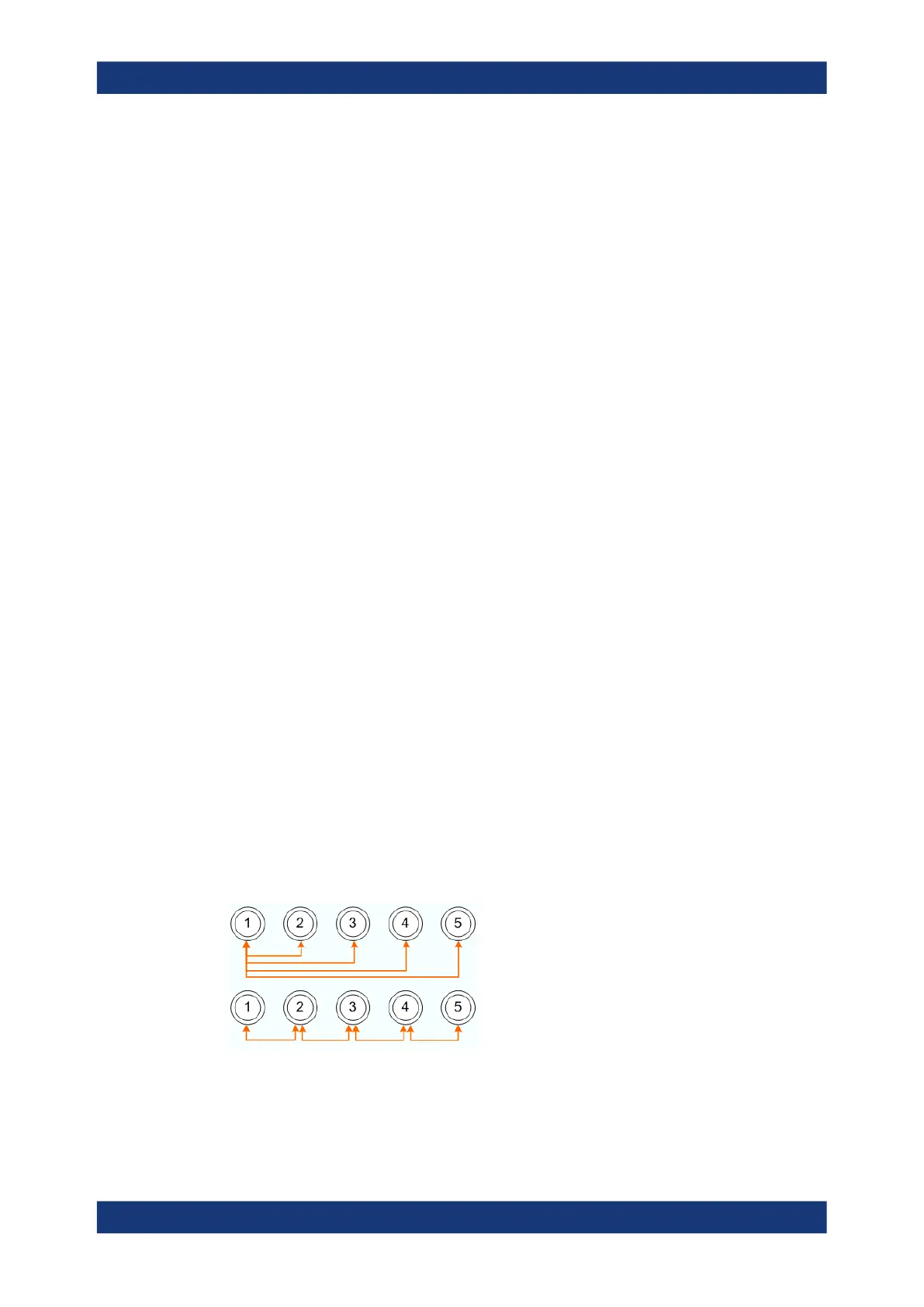
4.5.1.11 Full n-Port calibration with reduced number of Through connections
The analyzer can calculate the error terms for a full n-port calibration after n−1 Through
measurements, if the measured Throughs connect all ports to be calibrated. The cor-
rection values for the unmeasured Throughs can then be calculated from the mea-
sured ones.
To establish a sufficient set of Through connections, you can select an arbitrary test
port as the "center" and measure all Through connections to this test port ("star-sha-
ped calibration"). You can also connect all ports in increasing order, e.g. 1→2, 2→3,
3→4 ...
[For the mathematically inclined: the graph constructed from the calibration ports as
nodes and the measured Throughs as edges must be connected.]
Calibration

 Loading...


