GUI reference
R&S
®
ZNB/ZNBT
551User Manual 1173.9163.02 ─ 62
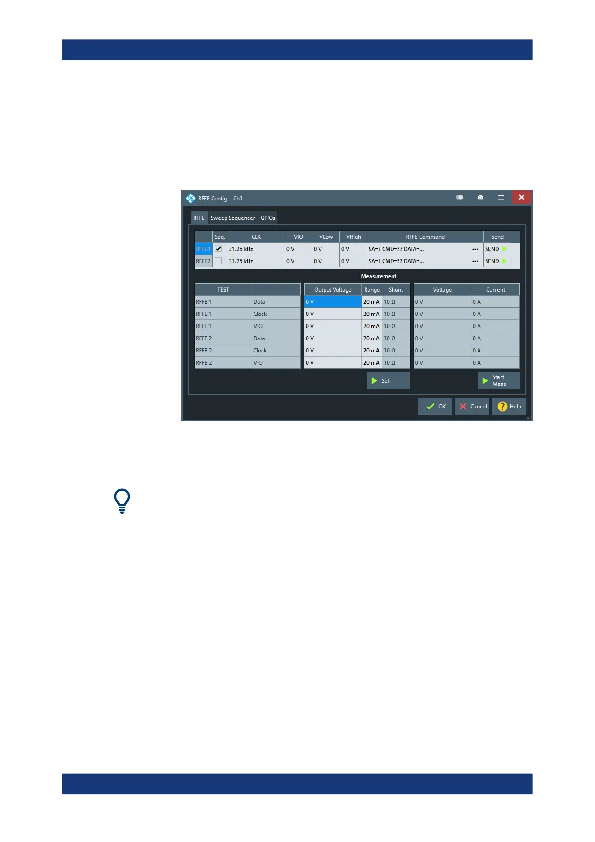
5.12.1.3 RFFE Config dialog for R&S ZN-B15/-Z15 Var. 03
Controls the channel-specific setup of the two RFFE bus interfaces and GPIO ports
provided by variant 03 of the internal/external RFFE GPIO extension board R&S ZN-
B15/-Z15.
Access: Channel – [Channel Config] > "Channels" > "RFFE..."
If the R&S ZNB is equipped with variant 02 of the extension board, a slightly different
user interface is shown. The "Measurement" columns are hidden and the remaining
content of the RFFE and GPIO tab are presented on a single "Control" tab.
Background information
Refer to Chapter 4.7.19, "RFFE GPIO interface", on page 257.
For more details about the voltage range, clock frequency ranges and their steps sizes,
refer to Chapter 12.3.5, "RFFE - GPIO interface", on page 1552.
RFFE tab
The "RFFE" tab is divided into two parts:
●
The upper part gives access to the RFFE interface settings and allows manual
command execution and result display (see "Basic RFFE interface settings and
command execution" on page 553)
●
The lower part allows you to define and apply test voltages and to execute voltage
and current measurements on the RFFE pins (see "GPIO voltage and current mea-
surements" on page 557)
The "Set" button activates the "Output Voltage" and "Range" ("Shunt" resistance) set-
tings. The "Meas" button starts the voltage and current measurements.
Channel Config softtool

 Loading...


