Getting started
R&S
®
ZNB/ZNBT
44User Manual 1173.9163.02 ─ 62
The test ports serve as outputs for the RF stimulus signal and as inputs for the mea-
sured RF signals from the DUT (response signals).
●
With a single test port, it is possible to generate a stimulus signal and measure the
response signal in reflection. For a measurement example, refer to Chapter 3.4.2,
"Reflection S-parameter measurement", on page 85.
●
With more than one test port, it is possible to perform full two-port, 3-port, ... , or n-
port measurements; see Chapter 4.3.1, "S-parameters", on page 125.
In the standard R&S ZNB configuration, all test ports are supplied by a common
source. Four-port instruments are available with an optional second source. For the
R&S ZNBT, an internal second source is automatically added if the instrument is
equipped with 12 ports or more.
●
Use a torque wrench when screwing RF cables on the test port connectors.
●
See also Chapter 3.1.5, "Considerations for test setup", on page 26.
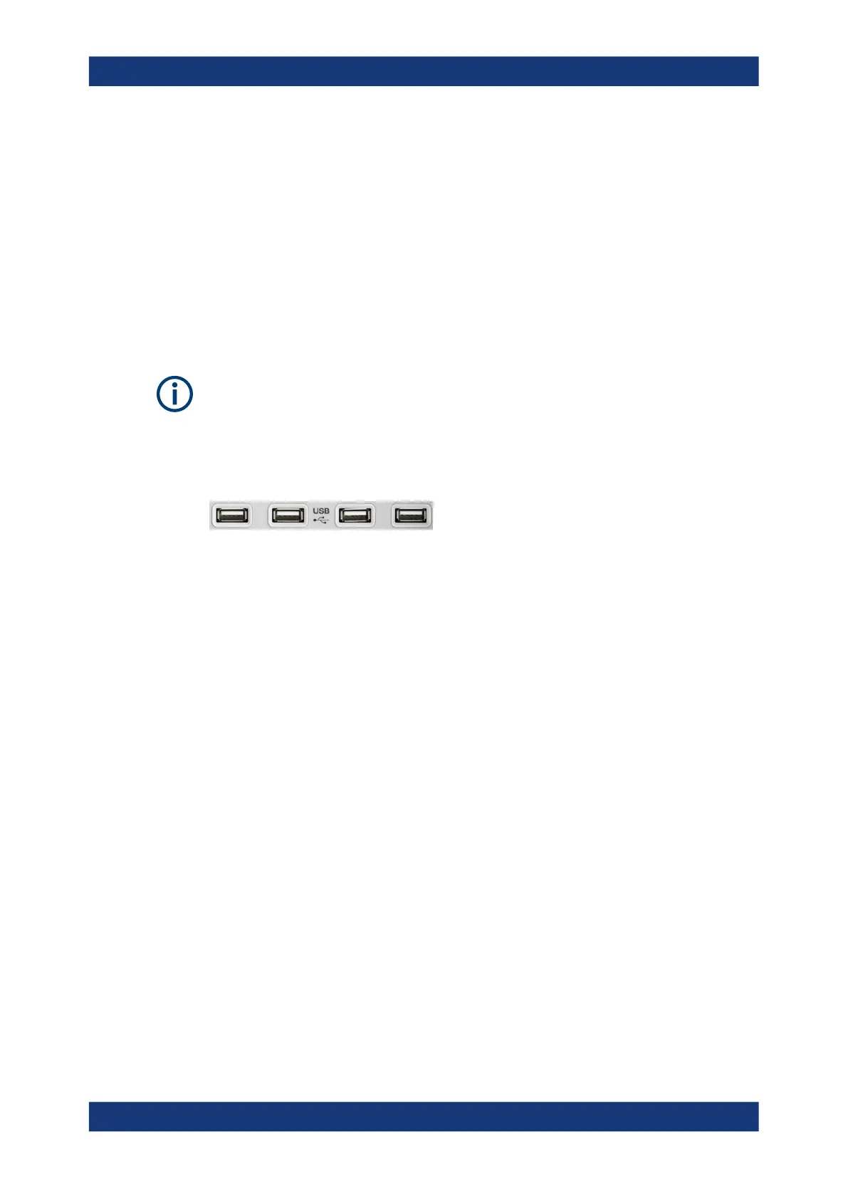
USB connectors
Four high-speed Universal Serial Bus connectors of type A (master USB).
The USB ports can be used to connect:
●
External PC accessories such as mouse or other pointing devices, a keyboard,
printer or external storage device (USB stick, CD-ROM drive etc.).
●
External measurement equipment such as a calibration unit, power meter, signal
generator or switch matrix.
3.2.2 Front panel R&S ZNBT
The largest part of R&S ZNBT front panel is reserved for the test ports, with an admin-
istrative area to the right. Brief explanations on the connectors and controls and the
rear panel can be found on the next pages.
Instrument tour

 Loading...


