Annexes
R&S
®
ZNB/ZNBT
1553User Manual 1173.9163.02 ─ 62
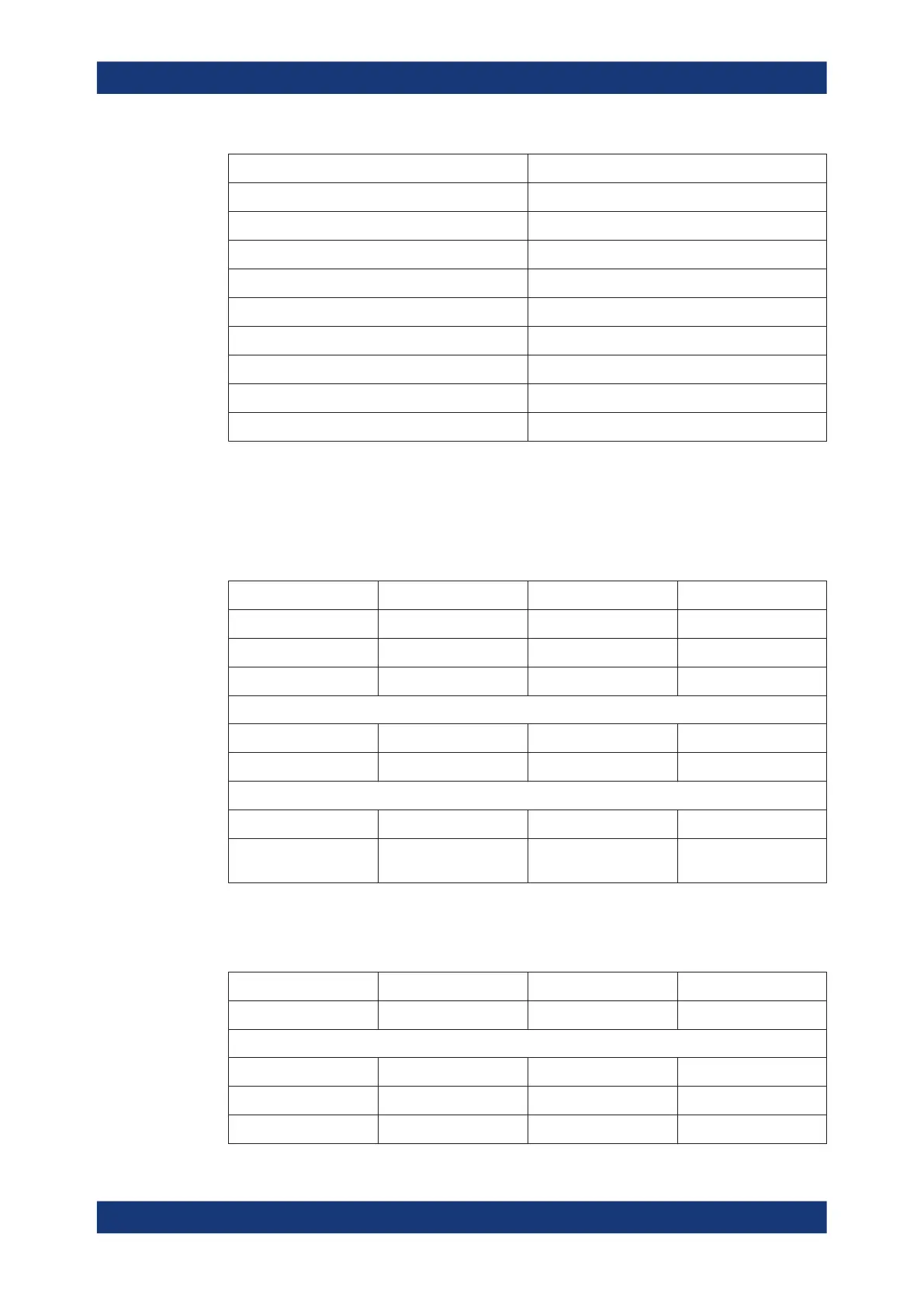
PIN number Comment
16 RFFE2_CLK
17 RFFE2_DATA
18 GPIO 1
19 GPIO 3
20 GPIO 5
21 GPIO 7
23 GPIO 10
24 For future use, please do not connect
25 For future use, please do not connect
12.3.5.2 Interface description
The values in the table below are typical values. See the R&S ZNB data sheet or the
R&S ZN-Z15 data sheet for details.
Table 12-3: RFFE bus interface
Parameter MIN [V] MAX [V] Step size [V]
IO voltage 0 2.5 0.001
Low voltage 0 2.5 0.001
High voltage 0 2.5 0.001
MAX [mA]
Current
20
MIN [kHz] MAX [kHz] Possible values [kHz]
Clock frequency 31.25 26000 52000/n with n=1664, ...,
2
All remaining data (e.g. rise time) are according to the specification v.1.00 of the MIPI
Alliance Group.
Table 12-4: GPIO Interface
Parameter MIN [V] MAX [V] Step size [V]
-7 +15 0.005
MAX [mA]
Current GPIO 1,...,8
20
Current GPIO 9,10
100
Interfaces and connectors

 Loading...


