Getting started
R&S
®
ZNB/ZNBT
46User Manual 1173.9163.02 ─ 62
●
both LEDs on: connector is used as a bidirectional (source and receive) port
3.2.2.2 Administrative area
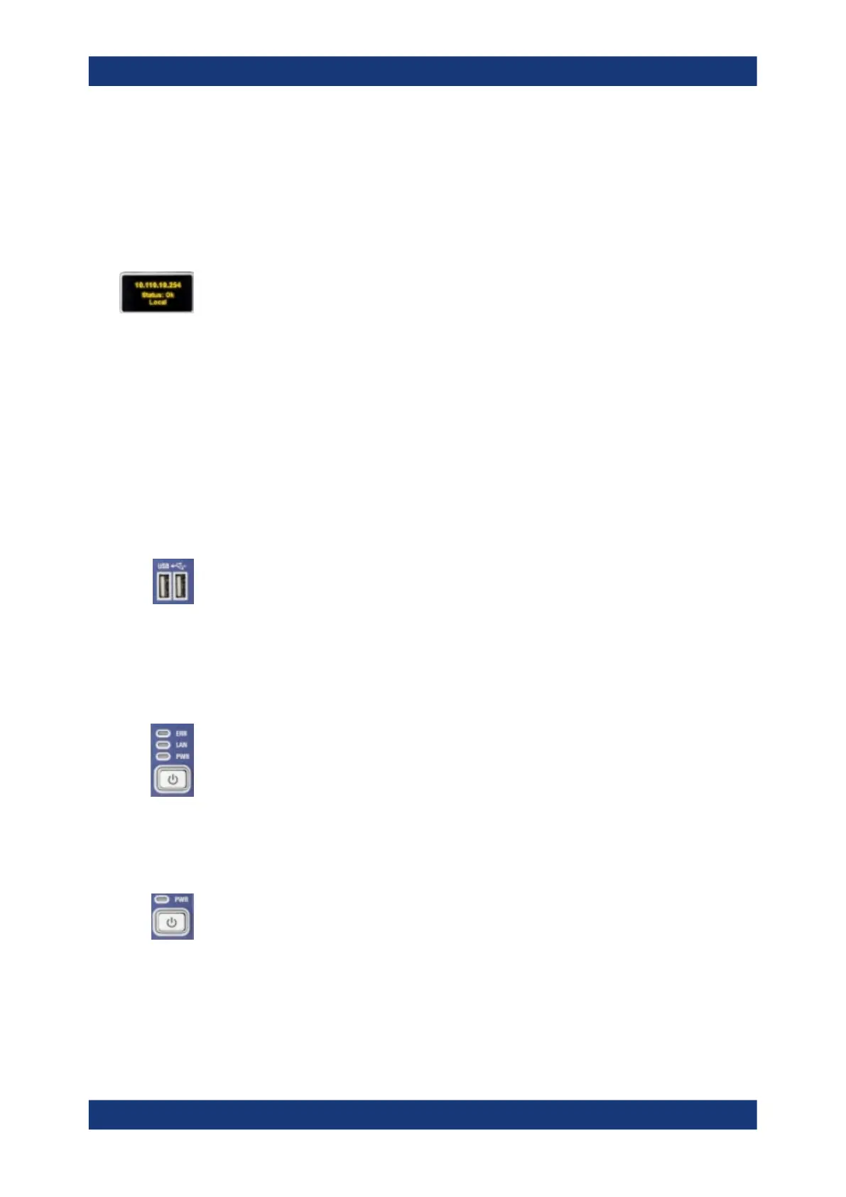
Mini display
A miniature display is provided in the upper right-hand corner of the front panel to pro-
vide the following instrument information:
●
IP address
●
Operational "Status" or "Error <error code>"
– "OK": no error
– Info: general errors (e.g. related to external devices or remote control)
– Warning: setting errors (e.g. generator power out of range)
– Error <error code>: severe errors (e.g. FW boot errors, HW errors)
●
Control mode:
– "Local": manual interaction (e.g. via Remote Desktop)
– "Remote": remote control (using a script) via a LAN or GPIB connection
USB Connectors
Two USB 2.0 connectors of type A (master USB) are provided on the front panel. They
can be used to connect:
●
External PC accessories such as mouse or other pointing devices, a keyboard,
printer or external storage device (USB stick, CD-ROM drive etc.).
●
External measurement equipment such as a calibration unit, power meter, signal
generator or switch matrix.
LED controls
Above the standby toggle switch some LEDs indicate various status information:
●
[ERR]: operation state; if an error occurs, the LED lights up red; for more informa-
tion on errors and troubleshooting see the R&S ZNB/ZNBT User Manual
●
[LAN]: LAN error occurred
●
[PWR]: power state (ready/standby); see Chapter 3.1.8, "Standby and ready state",
on page 29
Standby key
The standby key is located at the lower right-hand corner of the front panel. It serves
two main purposes:
●
Toggle between standby and ready state; see Chapter 3.1.8, "Standby and ready
state", on page 29.
●
Shut down the instrument; see Chapter 3.1.7, "Switching the instrument on and
off", on page 28.
Instrument tour

 Loading...


