Getting started
R&S
®
ZNB/ZNBT
51User Manual 1173.9163.02 ─ 62
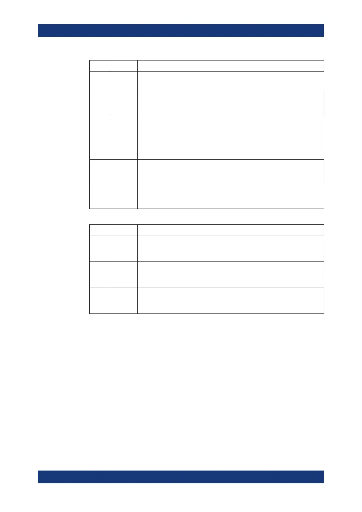
Index Label Description
10 REF OUT BNC output for the internal reference frequency of the R&S ZNBT. Use this connec-
tor to synchronize other instruments to the analyzer.
11 REF IN BNC input for an external reference frequency. Use this connector to synchronize
the R&S ZNBT to another device.
See Chapter 5.18.2, "Freq. Ref. tab", on page 776.
12 SYSTEM
DRIVE
Contains the removable system drive of the R&S ZNBT, containing all software
(including the operating system and the VNA application) and data. Do not remove
the system drive during operation.
Option R&S ZNBT-B19 provides an additional removable system drive (including
operating system and firmware). See Chapter 4.7.20, "Additional removable system
drive", on page 258.
13 (Ground
connector)
The ground connector provides the ground of the analyzer's supply voltage. Use this
connector for ESD protection; see "Preventing electrostatic discharge (ESD)"
on page 27.
14 Digital I/O Used to connect an external Handler I/O (option R&S ZNBT-Z14), providing a Cen-
tronics 36 input/output connector.
See Chapter 4.7.18, "Handler I/O (universal interface)", on page 256.
Table 3-5: Optional rear panel connectors
Index Label Description
15 DC INPUT Option R&S ZNBT-B81"DC Inputs" provides four BNC inputs for DC measurements
(adjustable to different voltage ranges).
See Chapter 5.2.11, "DC tab", on page 314.
16 Device
Control
This slot can be equipped with option R&S ZNBT-B12, providing a PCIe and a Direct
Control connector.
See Chapter 4.7.17, "Device control", on page 256.
17 GPIB Option R&S ZNBT-B10 provides a GPIB bus connector according to standard IEEE
488 / IEC 625.
See Chapter 12.3.3, "GPIB interface", on page 1541.
Match signals with 50 Ω to comply with EMC directives. See also Chapter 3.1.5, "Con-
siderations for test setup", on page 26.
3.3 Operating the instrument
The following sections describe the basics of manual operation, i.e. how to access
instrument functions and settings via the analyzer GUI. Manual operation is particularly
useful for getting to know the instrument and for trouble shooting.
Manual and remote control of the instrument
In contrast to the R&S ZNB, the R&S ZNBT is primarily intended to be remote-control-
led via the GPIB or LAN interface (see chapter 'Remote Control' in the user manual).
However, all instruments can be controlled manually, either using touchscreen and
frontpanel keys (R&S ZNB only), an external monitor in combination with a mouse (see
Operating the instrument

 Loading...


