Getting started
R&S
®
ZNB/ZNBT
50User Manual 1173.9163.02 ─ 62
1
2
12
3 4 5
8
13
11
15
76
9 10
14
16
17
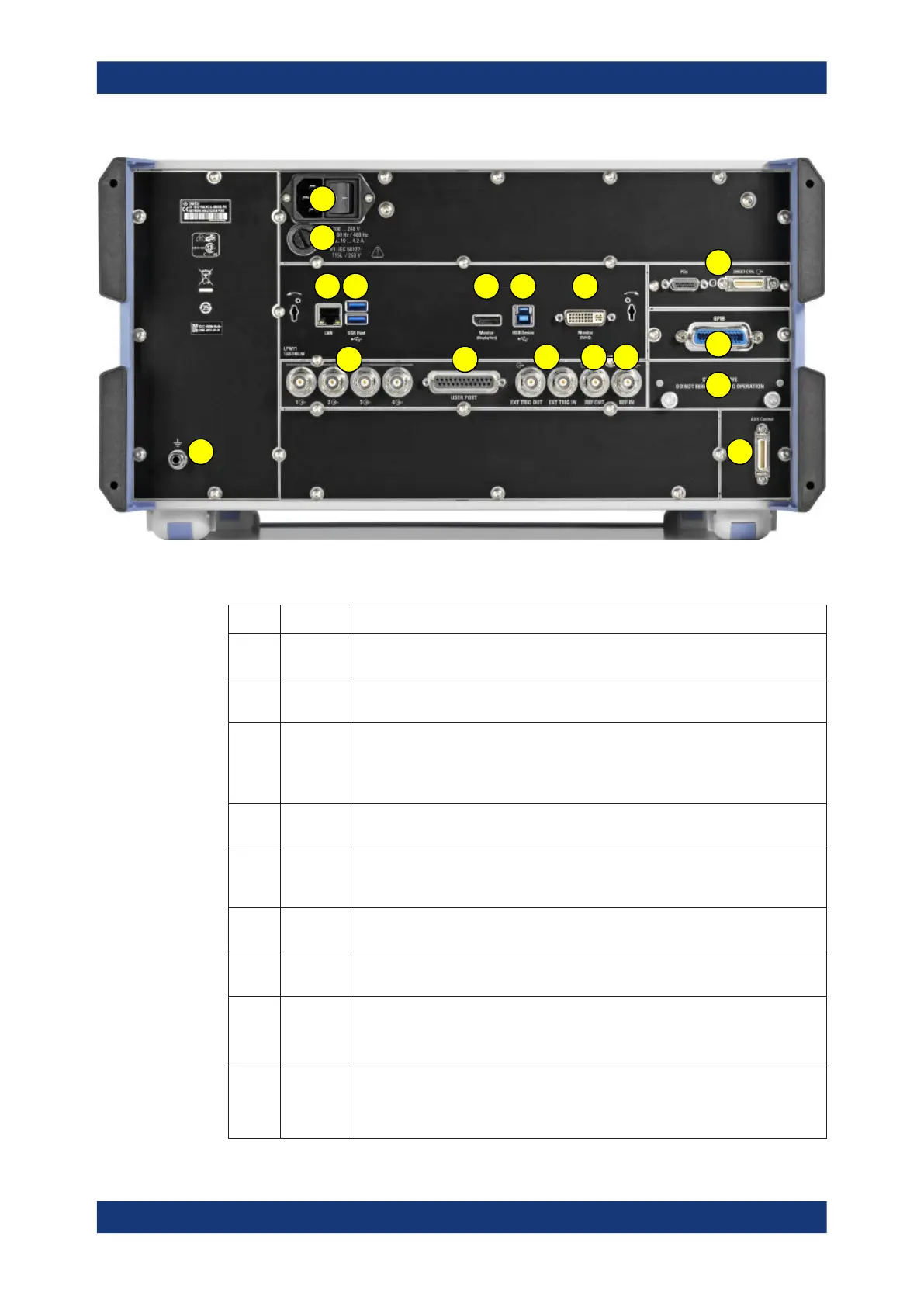
Figure 3-5: R&S
ZNBT rear view
Table 3-4: Rear panel connectors available on all instruments
Index Label Description
1 (Power
I/O)
Power on/off switch, see Chapter 3.1.7, "Switching the instrument on and off",
on page 28
2 (Fuse
holder)
Fuse holder, see Chapter 11.1, "Replacing fuses", on page 1535
3 LAN RJ-45 connector to integrate the instrument to a Local Area Network, primarily for
remote control purposes; see Chapter 3.1.12.1, "Assigning an IP address",
on page 35.
See also Chapter 12.3.2, "LAN interface", on page 1540.
4 USB /
USB Host
Two additional type A USB 3.0 host connectors; similar functionality as the type A
USB host connectors on the front panel (see "USB Connectors" on page 46).
5 Monitor
(Display-
Port)
External monitor connector (DisplayPort); see Chapter 3.1.11.1, "Connecting a moni-
tor", on page 32.
6 USB
Device
Type B USB 3.0 device (slave) connector for remote control of the instrument (see
Chapter 3.1.11.6, "Connecting a USB cable for remote control", on page 34)
7 Monitor
(DVI-D)
External monitor connector (DVI-D); see Chapter 3.1.11.1, "Connecting a monitor",
on page 32.
8 USER
PORT
25-pin D-Sub connector used as an input and output for low-voltage (3.3 V) TTL
control signals
See Chapter 12.3.1.1, "User Port", on page 1538.
9 EXT TRIG
IN / EXT
TRIG
OUT
Two BNC connectors for 5 V TTL external trigger signals
See Chapter 5.10.3, "Trigger tab", on page 437.
Instrument tour

 Loading...


