GUI reference
R&S
®
ZNB/ZNBT
557User Manual 1173.9163.02 ─ 62
Remote command:
CONTrol<Ch>:GPIO<Port>[:STATe]
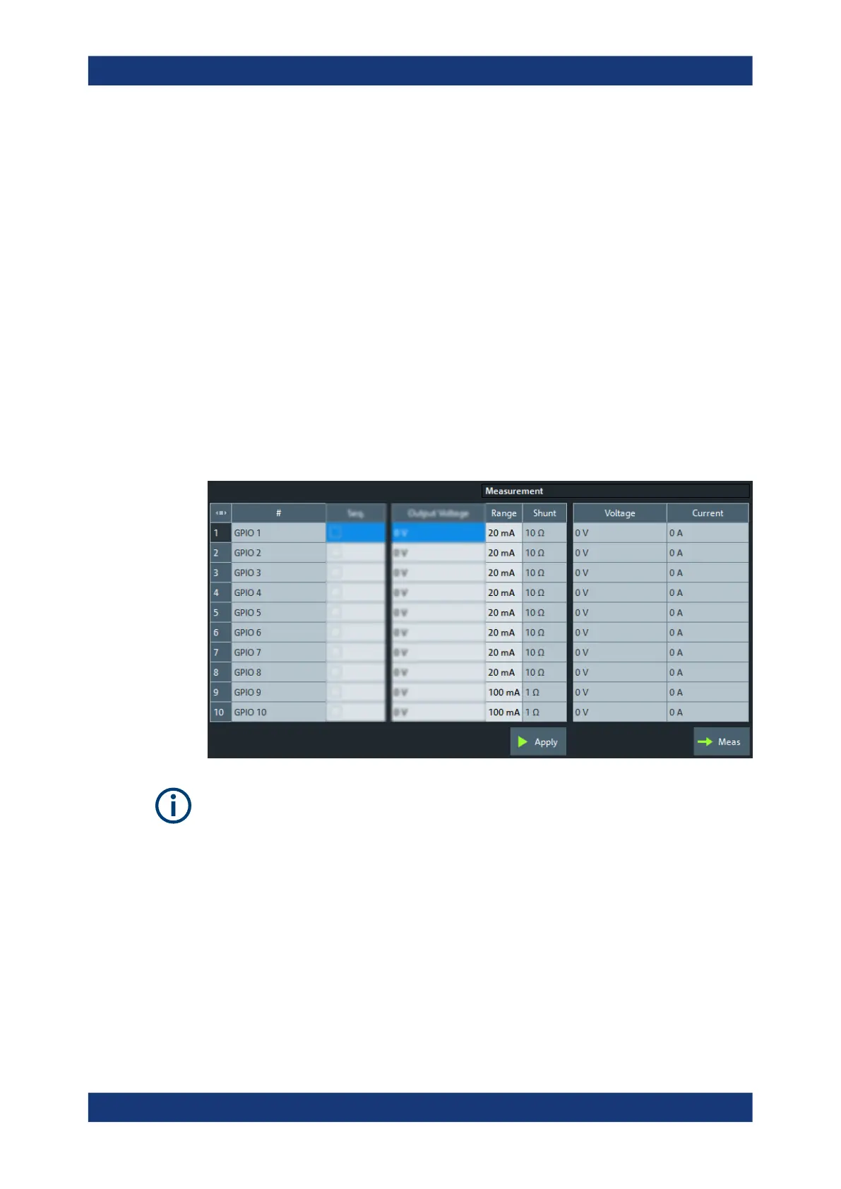
Voltage / Output Voltage
Sets the (default) voltage of the respective GPIO pin for R&S ZN-B15/-Z15 Var. 02 /
Var. 03.
Remote command:
CONTrol<Ch>:GPIO<Port>:VOLTage[:DEFault]
Apply
Use the "Apply" button to activate the configured voltage (and Range / Shunt) settings
to the GPIO pins.
Remote command:
CONTrol<Ch>:GPIO:VOLTage:OUTPut
GPIO voltage and current measurements
Defines and executes the voltage and current measurements on the GPIO pins.
●
The measurement parameters are channel-specific. However only one configura-
tion can be measured at a time.
●
Voltage and current measurements on the RFFE and GPIO pins are only possible
with Var. 03 of the extension board R&S ZN-B15/-Z15 (part number 1323.9355.03
or 1325.5905.03).
The high-resistance configuration of GPIO pins 9 and 10 requires FPGA version
6.1.0 or higher. For older versions of the R&S ZN-B15/Z15 Var. 03, pins 9 and 10
have the same current range as pins 1 to 8 (see "Range / Shunt" on page 558).
To check for an equipped RFFE/GPIO interface's part number and "Product Index"
version, see the Hardware tab of the "Info" dialog.
Channel Config softtool

 Loading...


