Annexes
R&S
®
ZNB/ZNBT
1551User Manual 1173.9163.02 ─ 62
Signal *RST Configuration
/OUTPUT 1, /OUTPUT 2 "High"
/SWEEP END "High"
/PASS_FAIL "High"
SCPI commands: CONTrol:HANDler:RESet (resets all configurable signals)
12.3.4.4 Timing of control Signals
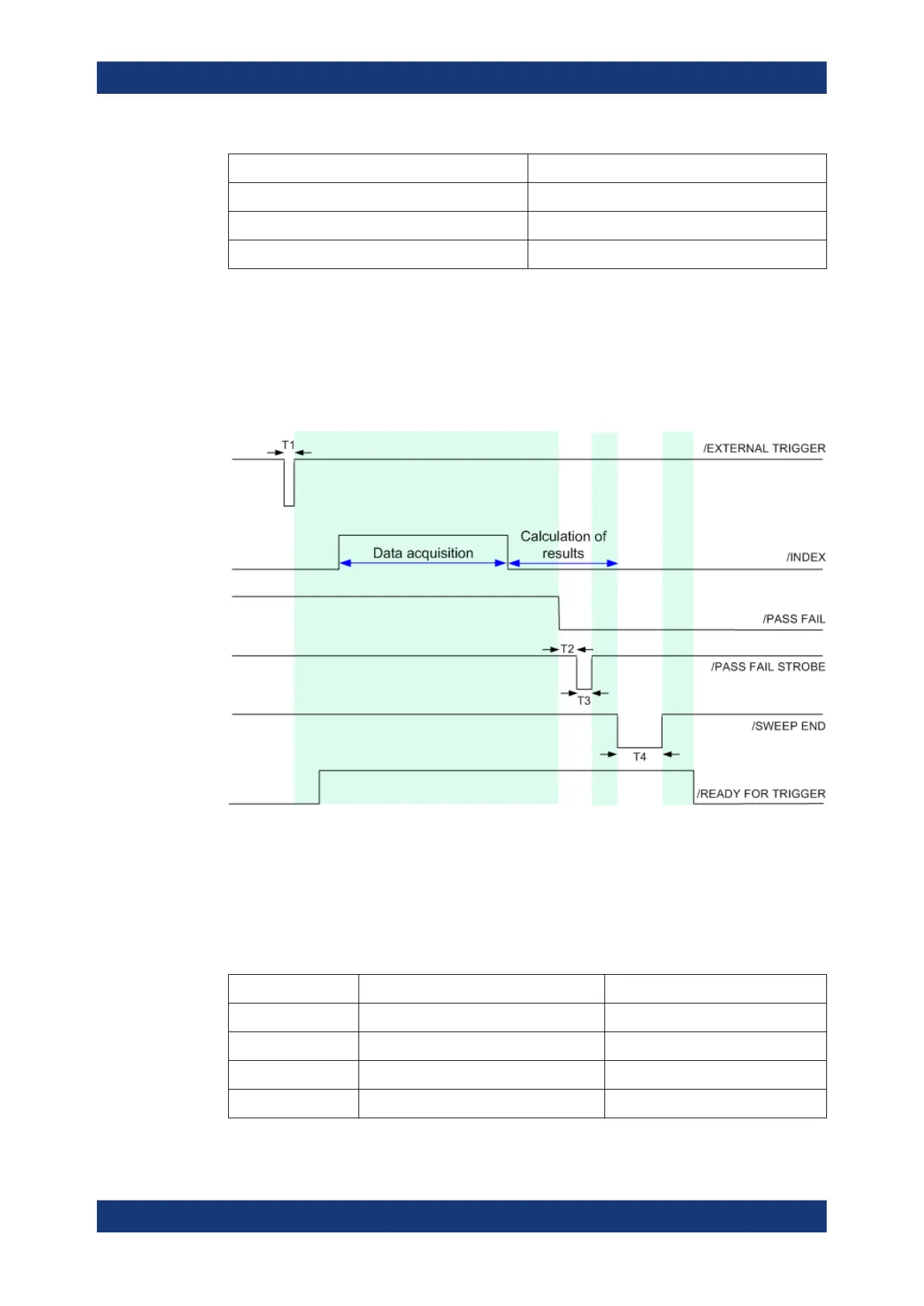
The timing of the essential measurement control signals is shown in the figure below.
The duration of the shaded time intervals depends on the measurement settings.
Figure 12-8: Timing of measurement control signals
The figure above corresponds to the default configuration of the /PASS FAIL signal.
For alternative configurations, refer to the documentation of the
CONTrol:HANDler:PASSfail... commands in Chapter 7.3.3, "CONTrol com-
mands", on page 1074. The figure contains the following pulse durations and response
times.
Time Description Value
T1 Pulse duration of /EXTERNAL TRIGGER Minimum value: 1 μs
T2 Response time of /PASS FAIL STROBE 1 μs
T3 Pulse duration of /PASS FAIL STROBE 1 μs
T4 Pulse duration of /SWEEP END 12 μs
Interfaces and connectors

 Loading...


