Concepts and features
R&S
®
ZNB/ZNBT
131User Manual 1173.9163.02 ─ 62
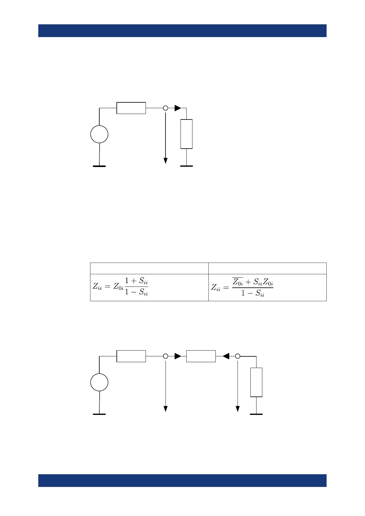
Reflection impedance
The converted impedance Z
ii
(1 ≤ i ≤n) describes the input impedance at port i of the
DUT.
U
0
I
1
U
1
Z
0i
Z
ii
Example:
For a 2-port DUT that is terminated at its output with the reference impedance Z
02
, Z
11
is the input impedance (matched-circuit impedance measured in a forward reflection
measurement).
A converted impedance Z
11
completely describes a one-port DUT.
The calculation formula of the converted reflection impedances Z
ii
depends on the
waveguide circuit theory according to which Reference impedances are calculated.
Table 4-4: Calculation of Converted Reflection Impedances
Traveling Waves Power Waves
Series transmission impedance
A two-port transmission parameter Z
ij
(i ≠ j) can describe a pure serial impedance
between the two ports.
U
0
I
1
I
2
U
1
U
2
U
0
Z
0j
Z
ij
Z
0i
The calculation formula of a converted serial transmission impedance Z
ij
depends on
the waveguide circuit theory according to which Reference impedances are calculated.
Measurement results

 Loading...


