Concepts and features
R&S
®
ZNB/ZNBT
132User Manual 1173.9163.02 ─ 62
Table 4-5: Calculation of Converted Series Transmission Impedances
Traveling Waves Power Waves
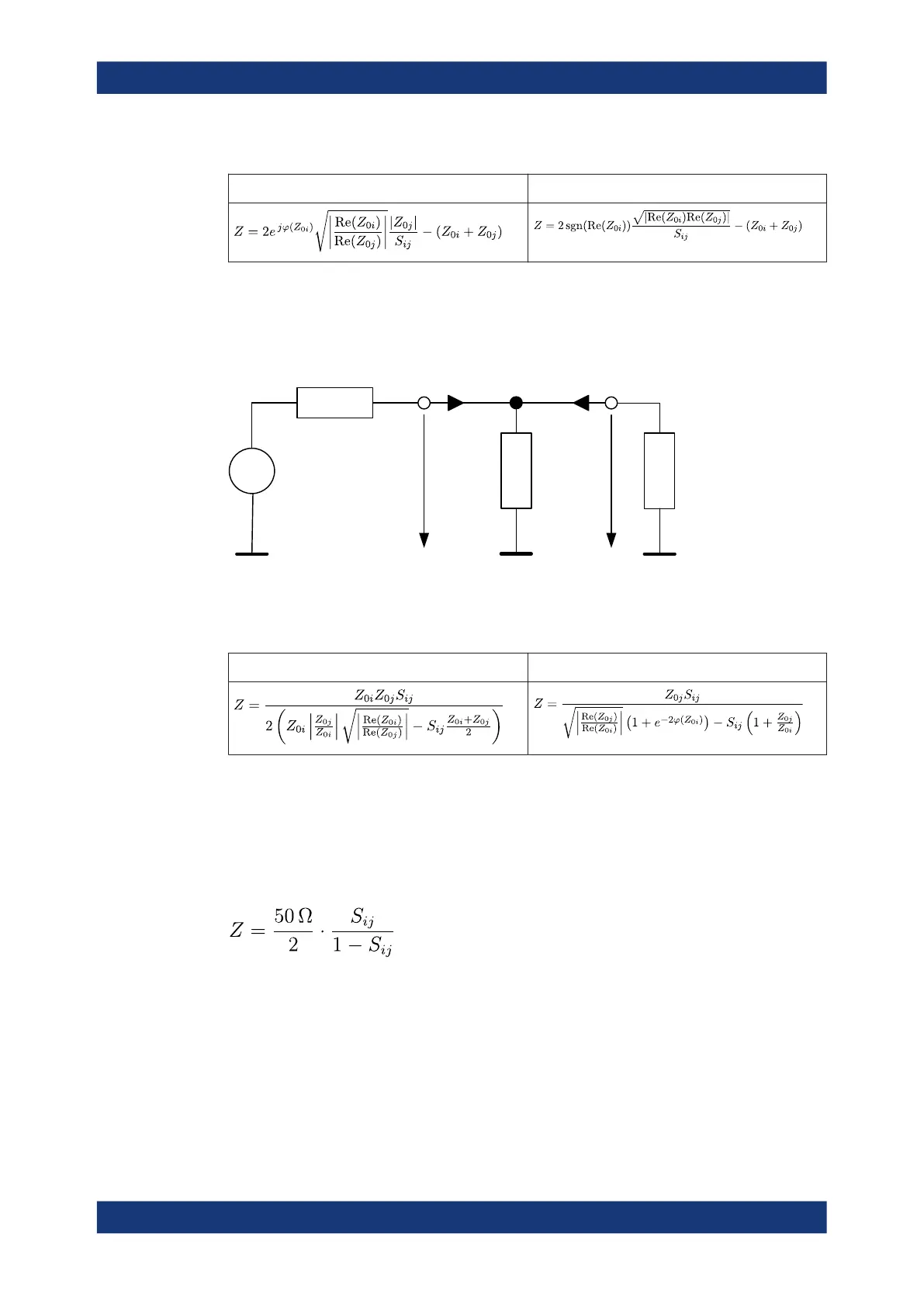
Parallel transmission impedance
A two-port transmission parameter Z
ij
(i ≠ j) can also describe a parallel impedance
between the two ports.
U
0
I
1
I
2
U
1
U
2
U
0
Z
0j
Z
ij
Z
0i
The calculation formula of a converted parallel transmission impedance Z
ij
depends on
the waveguide circuit theory according to which Reference impedances are calculated.
Table 4-6: Calculation of Converted Parallel Transmission Impedances
Traveling Waves Power Waves
Shunt-thru measurements
The shunt-thru method is used for measuring very low impedances. A typical applica-
tion are measurements on power distribution network (PDN) components, such as
bypass capacitors and DC-DC converters.
The R&S ZNB/ZNBT uses S
ij
(i≠j) to calculate the DUT impedance using the formula:
Measurement results

 Loading...


