Getting started
R&S
®
ZNB/ZNBT
45User Manual 1173.9163.02 ─ 62
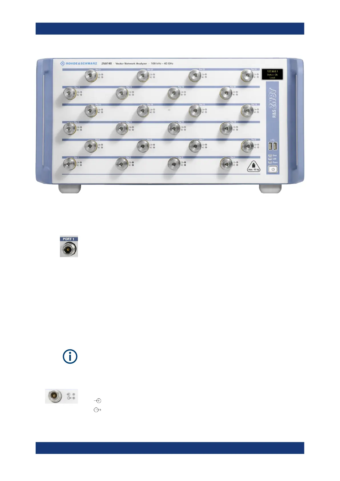
Figure 3-3: Front view of R&S
ZNBT40 (fully equipped with the maximum 24 ports)
3.2.2.1 Test ports
Numbered test port connectors:
●
Type N female connectors for the R&S ZNBT8. Depending on the equipped port
options there are 4, 8, 12, 16, 20 or 24 test ports.
●
3.5 mm male connectors for the R&S ZNBT20. Depending on the equipped port
options there are 8, 12, 16, 20 or 24 test ports.
●
2.92 mm (K) male connectors for the R&S ZNBT26 and R&S ZNBT40. Depending
on the equipped port options there are 8, 12, 16, 20 or 24 test ports.
The test ports serve as outputs for the RF stimulus signal and as inputs for the mea-
sured RF signals from the DUT (response signals). With a single test port, it is possible
to generate a stimulus signal and measure the response signal in reflection. For a
measurement example, refer to Chapter 3.4.2, "Reflection S-parameter measurement",
on page 85. With more than one test port, it is possible to perform full two-port, 3-
port, ... , or n-port measurements; see Chapter 4.3.1, "S-parameters", on page 125.
●
Use a torque wrench when screwing RF cables on the test port connectors.
●
See also Chapter 3.1.5, "Considerations for test setup", on page 26.
Connector usage
Two LEDs next to each test port indicate the connector usage:
●
on: connector is used as a source port
●
on: connector is used as a receive port
Instrument tour

 Loading...


