GUI reference
R&S
®
ZNB/ZNBT
568User Manual 1173.9163.02 ─ 62
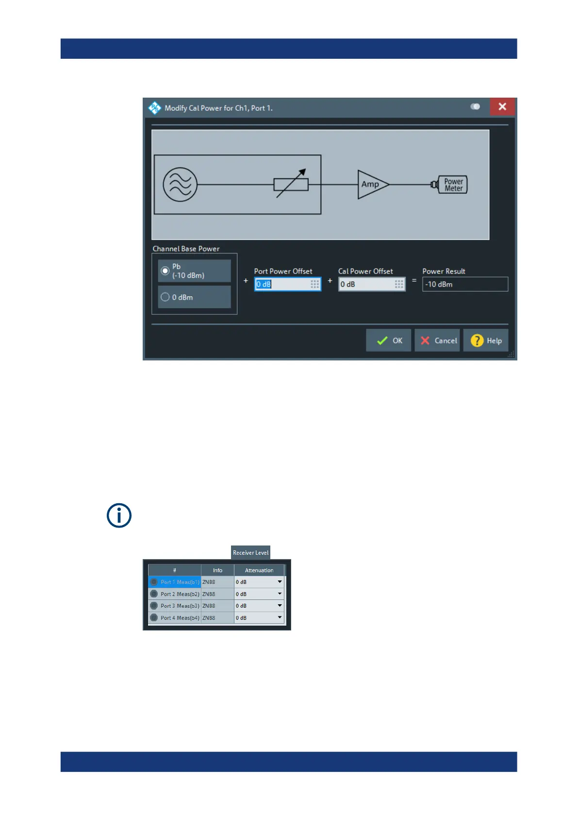
The control elements in the "Modify Cal Power" dialog are described in the following
sections:
●
"Channel Base Power" on page 528
●
"Port Power Offset" on page 528
●
"Cal Power Offset" on page 528
Receiver Level tab
Provides access to the receiver step attenuator settings.
Receiver step attenuators are optional hardware (see Chapter 4.7.23, "Receiver step
attenuators", on page 261).
Attenuation
Sets the attenuation at the respective measurement receiver (b-wave). See "Step
Attenuators" on page 417.
Remote command:
[SENSe<Ch>:]POWer:ATTenuation
Channel Config softtool

 Loading...


