Annexes
R&S
®
ZNB/ZNBT
1547User Manual 1173.9163.02 ─ 62
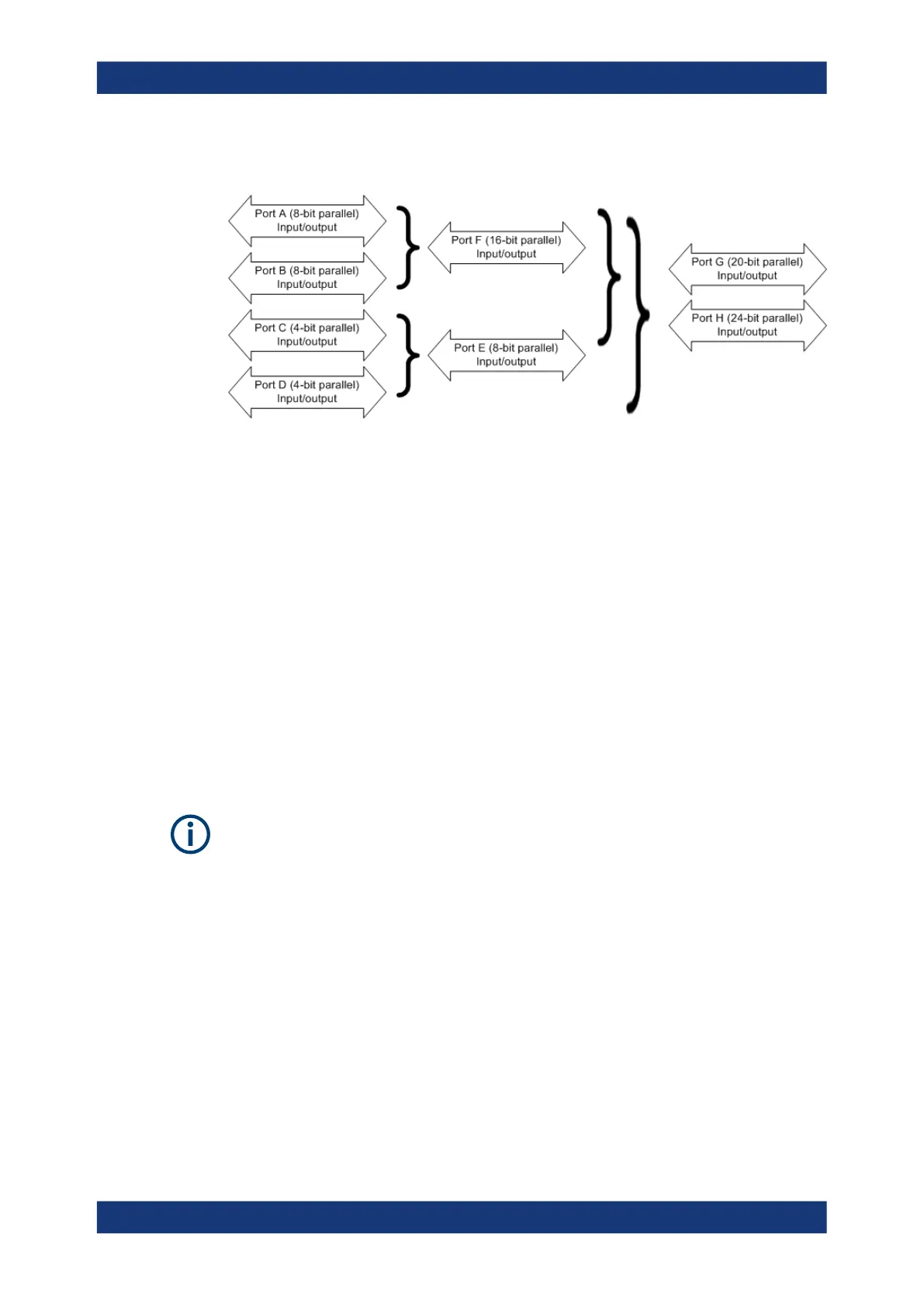
Figure 12-4: Definition of ports E, F, G, H
The properties of the combined ports are as follows:
●
The signal direction (input or output) is according to the configuration of ports A, B,
C, and D. E.g. to write data to port G (H), ports A, B, and C (A, B, C, and D) must
be configured as output ports.
●
Data can be read and written using the CONTrol:HANDler:E|F|G|H[:DATA]
commands.
●
The bit order is D3 ... D0 C3 ... C0 (port E), B7 ... B0 A7 ... A0 (port F), C3 ... C0
B7 ... B0 A7 ... A0 (port G), and D3 ... D0 C3 ... C0 B7 ... B0 A7 ... A0 (port H).
SCPI commands: See Chapter 7.3.3, "CONTrol commands", on page 1074
12.3.4.3 Universal iInterface connector
The Handler I/O (Universal Interface) option includes a Centronics 36 input/output con-
nector.
The R&S ZNB's internal Handler I/O option R&S ZN-B14 is placed in the right-hand
part of the network analyzer's rear panel. It must be installed by a Rohde & Schwarz
service representative.
The external Handler I/O option R&S ZNBT-Z14 can simply be connected to the Digital
I/O connector at the rear panel of the R&S ZNBT.
The pin assignment of the connector is shown below. A slash (/) at the beginning of the
signal name indicates that, by default, it is an active low (negative logic) signal.
Interfaces and connectors

 Loading...


