Concepts and features
R&S
®
ZNB/ZNBT
211User Manual 1173.9163.02 ─ 62
since the serial resistances are set to 0 Ω, the shunt resistances are set to 10 MΩ and
the shunt inductances are set to 0 Siemens.
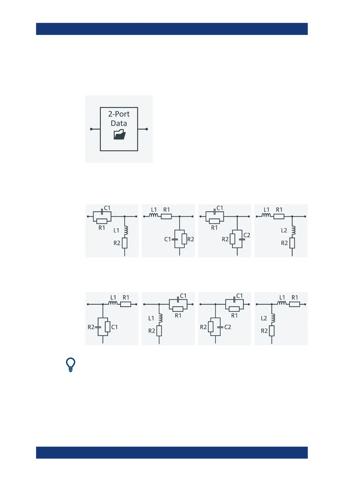
The first network is defined by its S-parameters stored in an imported two-port Touch-
stone file (*.s2p). No additional parameters are required.
The following networks are composed of a serial capacitance C or inductance L (as
seen from the test port), followed by a shunt L or C. They are named
Serial C, Shunt L / Serial L, Shunt C / Serial C, Shunt C /
Serial L, Shunt L.
The following networks are composed of a shunt C or L (as seen from the analyzer
port), followed by a serial C or L. They are named Shunt C, Serial L /
Shunt L, Serial C / Shunt C, Serial C / Shunt L, Serial L.
At the GUI, the "capacitance C<i> in parallel with resistance R<i>" circuit blocks can be
replaced by equivalent "capacitance C<i> in parallel with conductance G<i>" circuit
blocks.
In addition, there is also a Shunt L, Shunt C circuit model available, where the
shunt C is defined as a capacitance C in parallel with a conductance G:
Offset parameters and de-/embedding

 Loading...


