Concepts and features
R&S
®
ZNB/ZNBT
242User Manual 1173.9163.02 ─ 62
ples. These intermodulation products can be near the upper and lower tone frequen-
cies, as long as their order is odd.
The analyzer measures the intermodulation products of k
th
order IMk (where k = 3, 5,
7, 9) at the lower tone frequency minus (k – 1)/2 times the tone distance and at the
upper tone frequency plus (k – 1)/2 times the tone distance; see also "Intermodulation
measurement results" on page 244.
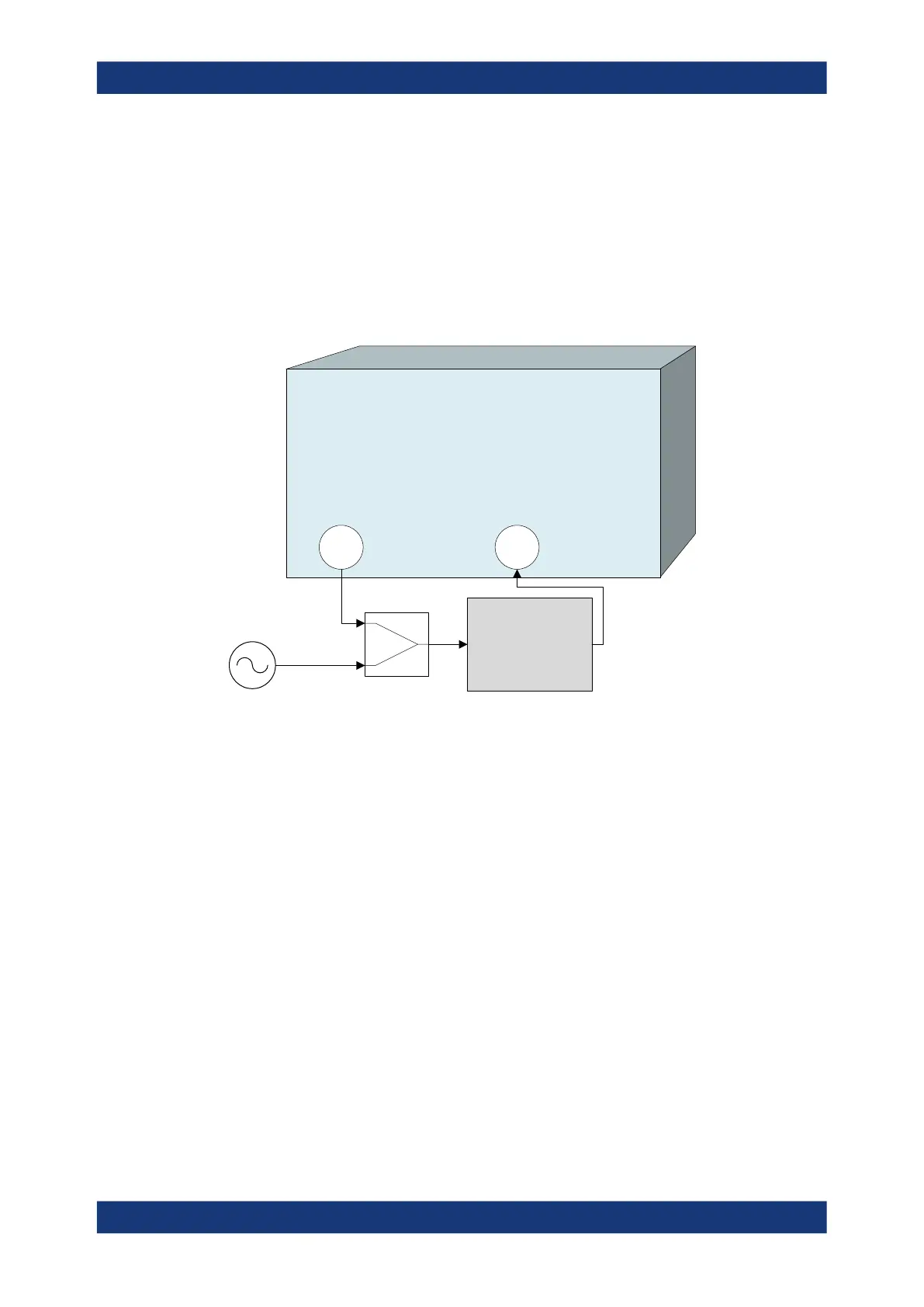
For a two-port R&S ZNB, a test setup with an external generator and a combiner is
required.
VNA
1 2
Upper Tone
DUT
1 2
Lower Tone
The lower tone signal is generated at port 1, the upper tone is provided by the external
generator. Both signals are combined externally and fed to the DUT input. The intermo-
dulation quantities can be measured at the DUT output (transmitted wave b2). It is pos-
sible to interchange the ports no. 1 and 2.
For a R&S ZNB/ZNBT with two internal sources, you can use any combination of ana-
lyzer ports that are supplied by different internal sources to generate the lower and
upper tones (see Chapter 4.7.14, "Internal second source", on page 255). In the follow-
ing example, port 3 of a R&S ZNB replaces the external generator. For a R&S ZNBT
with more than 8 ports the lower and upper tone could be provided by ports 1 and 9,
for example.
Optional extensions and accessories

 Loading...


