Getting started
R&S
®
ZNB/ZNBT
48User Manual 1173.9163.02 ─ 62
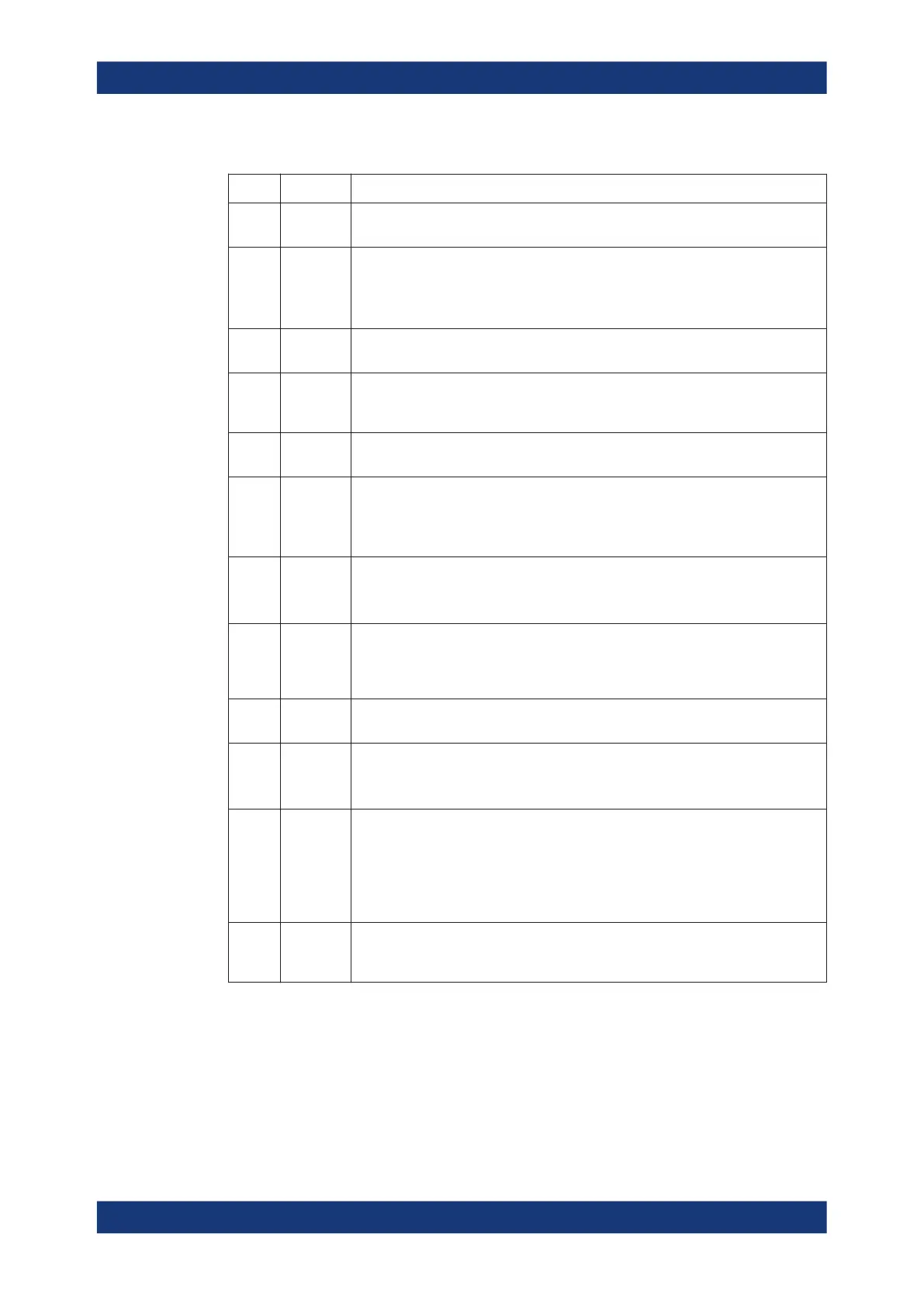
Table 3-2: Rear panel connectors available on all instruments
Index Label Description
1 (Power
I/O)
Power on / off switch, see Chapter 3.1.7, "Switching the instrument on and off",
on page 28
2 LAN RJ-45 connector to integrate the instrument to a Local Area Network, primarily for
remote control purposes; see Chapter 3.1.12.1, "Assigning an IP address",
on page 35.
See also Chapter 12.3.2, "LAN interface", on page 1540.
3 USB /
USB Host
Two additional type A USB 3.0 host connectors; similar functionality as the USB con-
nectors on the front panel (see "USB connectors" on page 44).
4 Monitor
(Display-
Port)
External monitor connector (DisplayPort); see Chapter 3.1.11.1, "Connecting a moni-
tor", on page 32.
5 USB
Device
Type B USB 3.0 device (slave) connector for remote control of the instrument (see
Chapter 3.1.11.6, "Connecting a USB cable for remote control", on page 34)
6 Monitor
(DVI-D) /
HDMI
External monitor connector
●
DVI-D for 1st generation R&S ZNB
●
HDMI for 2nd generation R&S ZNB
See Chapter 3.1.11.1, "Connecting a monitor", on page 32.
7 USER
PORT
25-pin D-Sub connector used as an input and output for low-voltage (3.3 V) TTL
control signals
See Chapter 12.3.1.1, "User Port", on page 1538.
8 EXT TRIG
IN / EXT
TRIG
OUT
Two BNC connectors for 5 V TTL external trigger signals
See Chapter 5.10.3, "Trigger tab", on page 437.
9 REF OUT BNC output for the internal reference frequency of the R&S ZNB. Use this connector
to synchronize other instruments to the analyzer.
10 REF IN BNC input for an external reference frequency. Use this connector to synchronize
the R&S ZNB to another device.
See Chapter 5.18.2, "Freq. Ref. tab", on page 776.
11 (System
drive)
Contains the removable system drive of the R&S ZNB, containing all software
(including the operating system and the VNA application) and data. Do not remove
the system drive during operation.
Option R&S ZNB-B19 provides an additional removable system drive (including
operating system and firmware). See Chapter 4.7.20, "Additional removable system
drive", on page 258.
12 (Ground
connector)
The ground connector provides the ground of the analyzer's supply voltage. Use this
connector for ESD protection; see "Preventing electrostatic discharge (ESD)"
on page 27.
Instrument tour

 Loading...


