Command reference
R&S
®
ZNB/ZNBT
975User Manual 1173.9163.02 ─ 62
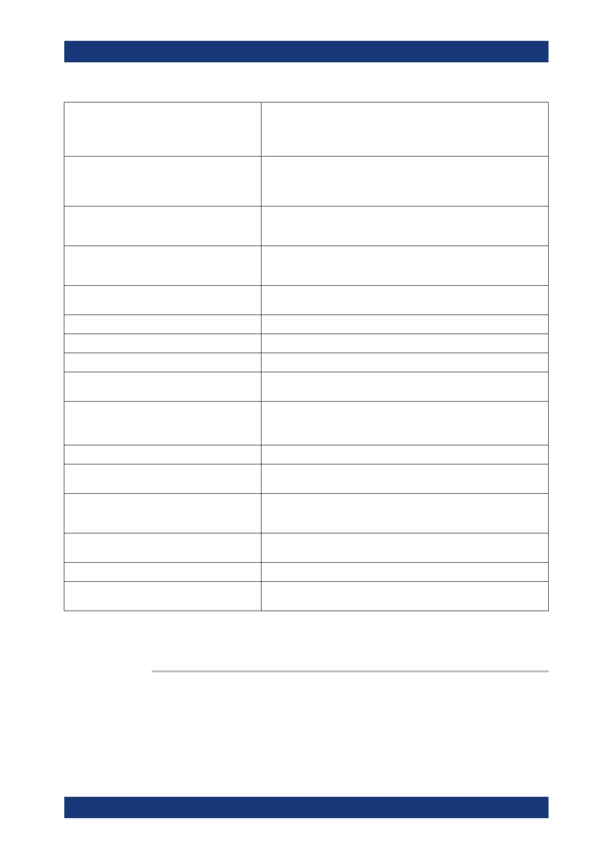
'B2D1/A1D1' | ... 'B02D01/A01D01' | ...
... | 'B2D1/A1D1SAM' | 'B2D1/A1D1AVG' 'B2D1/
A1D1AMP' | ...
Ratios of wave quantities with drive ports
The strings SAM, AVG, AMP appended to the wave quantities denote a nor-
mal (sample, SAM), AVG Real Imag (AVG), or AVG Mag Phase (AMP)
detector.
'B2G1/A1G1' | ... 'B02G01/A01G01' | ... 'B2G1/
A1G1SAM' | 'B2G1/A1G1AVG' 'B2G1/A1G1AMP'
| ...
Ratios of wave quantities with port numbers and external generator providing
the stimulus signal (G<no> for generator no.). The strings SAM, AVG, AMP
appended to the wave quantities denote a normal (sample, SAM), AVG Real
Imag (AVG), or AVG Mag Phase (AMP) detector.
'IMB21' | 'IMB12' | 'IMB31' | ... Imbalance parameter Imb<receive_port><drive_port> for logical port num-
bers <receive_port> and <drive_port>. The logical ports must be different
and at least one of them must be balanced.
'CMRR11' | 'CMRR21' | 'CMRR12' | 'CMRR22' | ... Common mode rejection ratio CMRR<receive_port><drive_port> parameter
for logical port numbers <receive_port> and <drive_port>, at least one of
them balanced.
'IMB1-23' | 'IMB23-1' | 'IMB1-24' | ... Differential Imbalance parameters between a balanced and two single-ended
logical ports
'KFAC21' | 'KFAC12' | ... Stability factor K (for unbalanced ports only)
'MUF121' | 'MUF112' | ... Stability factor 1 (for unbalanced ports only)
'MUF221' | 'MUF212' | ... Stability factor 2 (for unbalanced ports only)
'Pmtr1G1' | 'Pmtr2G1' | 'Pmtr3D1' | ... Power sensor measurement using a power meter 'Pmtr<no>' and either an
external generator 'G<no>' or an analyzer source port 'D<no>'
'DC1D1' ... 'DC4D1' | 'DC1D01' ... 'DC4D01'
'DC1V' | 'DC10V'
DC measurement DC 1 to DC 4. D1 or D01 etc. denotes the (logical) drive
port
For R&S ZVAB compatibility; query returns 'DC1D1' or 'DC2D1')
'PAE21' | PAE12' | ... Power added efficiency (referring to logical ports)
'IM3UO' | 'IM3LO' | 'IM3MO' | 'IM5UO' ... 'IM9MO' Intermodulation product IM<order><side><at DUT> where <order> = 3 | 5 | 7
| 9, <side> = U | L | M (for upper or lower or major), at DUT output
'IM3UOR' | 'IM3LOR' | 'IM3MOR' | 'IM5UOR' ...
'IM9MOR'
Intermodulation product (as explained above) displayed in dB units relative
to the measured lower tone level at DUT output ("intermodulation suppres-
sion")
'IP3UO' | 'IP3LO' | 'IP3MO' | 'IP5UO' ... 'IP9MO' Intercept point IP<order><side>O where <order> = 3 | 5 | 7 | 9, <side> = U |
L | M (for upper or lower or major), at DUT output
UTI | UTO | LTI | LTO Upper or lower tone at DUT input or output
Cu(P<Src Port>)<_lowercase_ext_dll_name>/<Task
Type>/<Additional Input>
Traces calculated using external DLL <ext_dll_name>.dll.
*) Selecting a parameter Y...<n><m> or Z...<n><m> sets the range of port numbers to
be considered for the Y and Z-parameter measurement to <n>:<m>.
CALCulate<Ch>:PARameter:SDEFine:SENDed <TraceName>, <Result>
Creates a trace and assigns a channel number, a name and a measurement parame-
ter to it. The trace becomes the active trace in the channel but is not displayed.
SCPI command reference

 Loading...