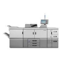
Specifications
SM 7-39 D014/D015/D078/D079
Specifications
PCBs
PCB1
PFB (Paper Feed
Board)
Controls paper trays and paper feed.
PCB2 AC Drive Board
Controls the power supply to the fusing lamps, heaters,
and PSU.
PCB3
PSU (Power Supply
Unit)
Supplies DC current to the machine and contains the
AC drive that controls the fusing lamp power supply.
PCB4 DRB (Drive Board)
Contains the circuits for the stepping motors that drive
the printer engine, and distributes electrical power to all
other PCBs.
PCB5
Power Pack:
Development Bias
Supplies the voltage for the bias applied to the
developer in the PCUs by the development rollers.
PCB6 Power Pack: Charge
Supplies the voltage for the charge applied to the OPC
drums by the charge roller.
PCB7
Power Pack:
Transfer
Supplies charge to 1) the four image transfer rollers that
pull the toner images from the four from the four drums
(Y, M, C, K), and 2) to the paper transfer roller that pulls
the image off the ITB onto paper.
PCB8
Power Pack -
Separation
Supplies the dc/ac charges for paper separation.
PCB9
DTMB
(Drum/Transfer
Motor Board)
Controls the motors that drive the OPC drums and ITB.
PCB10 IPU
Performs: 1) Image processing control, 2) GW controller
interface, 3) peripheral timing control.
PCB11
Potential Sensor
Board
Processes data from the Y, M, C, K, potential sensors.
Rev. 04/2008