Process Control
D014/D015/D078/D079 6-56 SM
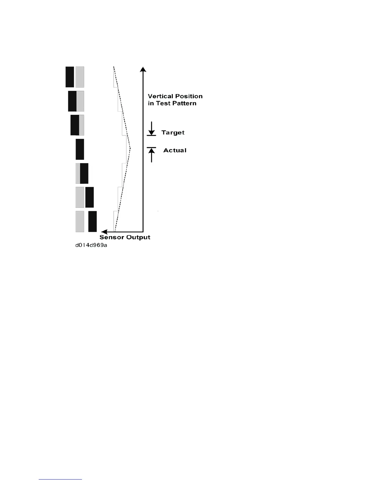
This diagram shows a close-up view of the main-scan test pattern.
K is the reference, and the positions of CMY are adjusted with reference to the K pattern.
The CMY patterns are vertical (shown in grey in the diagram), but the K pattern overlaps
the CMY patterns as shown.
The MUSIC sensor response is measured. The output is the lowest when the K pattern
fully overlaps the color pattern (the dotted lines in the diagram cross at this point). This is
the "Actual" position as shown in the diagram. But there is a "Target" value in the machine
software (an example is shown in the diagram; this is not the real target, it is just an
example to explain the process). The machine compares the "Actual" and "Target" values,
and adjusts the laser timing in response to the results of this comparison.
Skew is also measured in the main scan direction using the patterns at the left and right of
the ITB. If skew is detected, the machine adjusts the angle of the 3rd mirrors.