GUI reference
R&S
®
ZNB/ZNBT
728User Manual 1173.9163.02 ─ 62
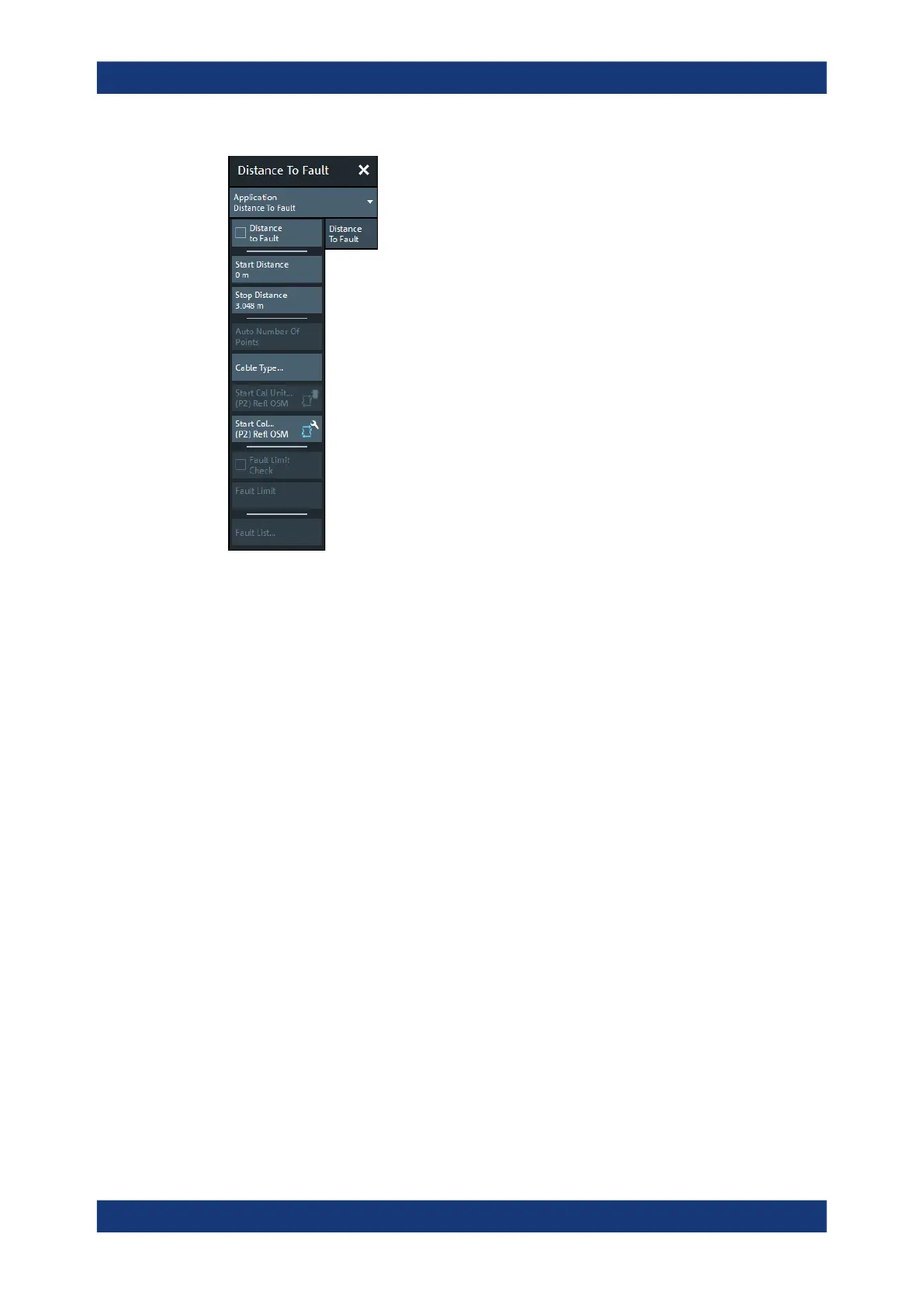
A standard DtF measurement is prepared in the order from top to bottom:
1. Enable DtF measurement, see "Distance to Fault" on page 728
2. Configure the distance window, see "Start Distance / Stop Distance" on page 729
3. Adjust the number of sweep points (and, if necessary, the frequency span), see
Auto Number of Points
4. Select (or define and select) a suitable cable type, see"Cable Type..."
on page 730
5. Perform a full one-port calibration at physical port 2, see "Start Cal Unit... (P2) Refl
OSM / Start Cal... (P2) Refl OSM" on page 731
You should now be able to locate the faults (peaks) by examining the trace.
You can also let the firmware generate a list of faults by enabling Fault Limit Check
and defining a suitable Fault Limit. Use Fault List... to display (and export) the
detected faults.
Distance to Fault
Activates/deactivates Distance to Fault representation for the active trace.
Note that "Distance to Fault" can only be enabled, if the active channel is configured to
perform a linear frequency sweep.
If the active trace is a reflection trace S
ii
, the analyzer firmware assumes that the DUT
is connected to port p=i. Otherwise it assumes that the DUT is connected to port p=2.
When activating "Distance to Fault", the analyzer firmware
●
sets S
pp
as measured quantity of the active trace
●
proposes a reflection normalization at port p (see "Start Cal Unit... (P2) Refl OSM /
Start Cal... (P2) Refl OSM" on page 731)
Applic softtool

 Loading...


