Punch Unit B831
D014/D015/D078/D079 1-114 SM
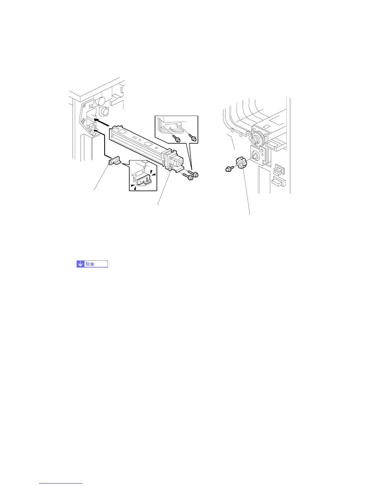
11. Position the 2 mm spacer [A] and attach the punch unit [B] (Screw x 2, M3 x 10).
12. Use one of the screws removed from the motor protector plate to fasten the remaining
two spacers to the frame as shown.
These extra spacers can be used to adjust the position of the punch holes (front to rear,
across the page).
13. At the front, fasten the punch unit knob [C] (Screw x 1).
B831I105.WMF
B831I108.WMF
[A]
[B]
[C]
Rev. 03/2008