EPSON AcuLaser CX11/CX11F Revision B
OPERATING PRINCIPLES Scanner Operating Principles 124
2.3 Scanner Operating Principles
This section describes operating principles of the scanner and ADF of the AcuLaser
CX11/CX11F.
2.3.1 Scanner Mechanism Overview
The scanner is a flatbed scanner with 600 dpi optical resolution and supports up to A4
or Letter/Legal document size. The internal mechanism is broadly divided into two
parts; Carriage Unit that includes the light source and CCD sensor, and Carriage Drive
Mechanism.
CARRIAGE UNIT
CCD Sensor Board : Includes a Color CCD line sensor and a control circuit for
the sensor.
Light source : White cold cathode fluorescent lamp (CCFL)
Inverter Board : Generates a voltage for the light source (Rises positive 24
VDC, and converts it to AC Voltage).
Mirror/Lens : Leads the light reflected from document to the CCD sensor.
CARRIAGE DRIVE MECHANISM
CR Motor : A four-phase pulse motor with 96 poles. Driven and
controlled by the driver circuit which uses PWM (pulse-
width modulation) current control system.
Carriage Mechanism:Moves the Carriage Unit to the sub scanning direction by
driving of the CR motor on the Carriage Shaft which
supports one side of the Carriage Unit.
Home sensor : A transparent sensor attached to the bottom of the Carriage
Unit. Detects the carriage home position by detecting the
flag located near the home position in the lower case of the
scanner unit.
OTHERS
Magnet sensor : Detects the open/close status of the document cover or
the ADF. It is attached on the backside of the upper
case of the scanner unit. When the sensor detects that
the document cover or the ADF is opened while the
scanner is in standby mode, the scanner lamp is turned
on and the Carriage Unit moves to its home position.
Carriage Lock Mechanism: Locks the Carriage Unit to protect it during
transportation. To lock the Carriage Unit, set the
sliding lock lever on the upper case of the scanner unit
to LOCK position.
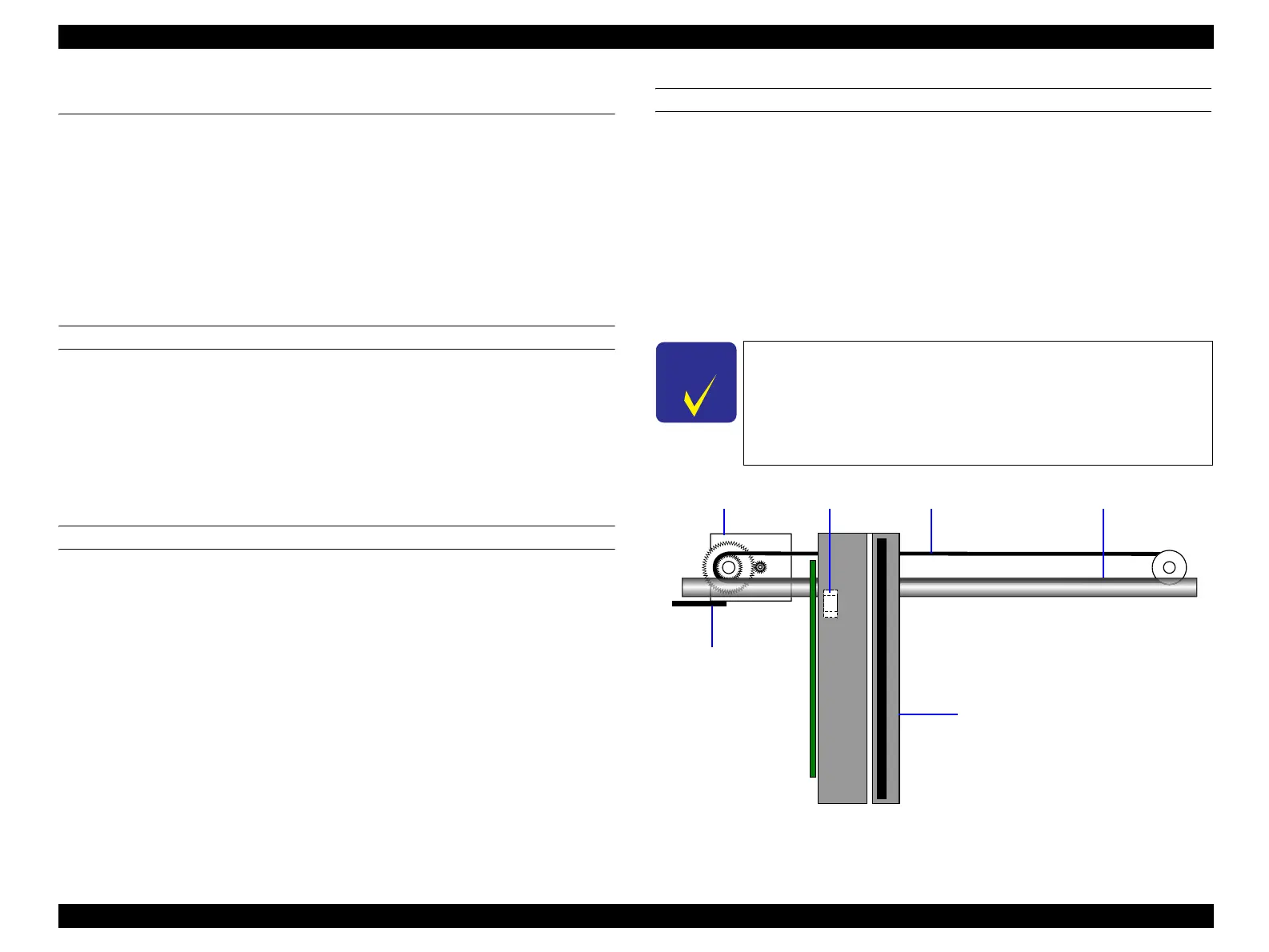
Figure 2-59. Key Components of the Scanner Mechanism
C H E C K
P O I N T
Make sure to unlock the Carriage Unit (set the sliding lock
lever to unlock position) before turning the power on.
When the product should be transported for some reason,
move the Carriage Unit to the lock position using the control
panel “Printer Engine Restrictions” (p39) and then lock the
unit with the sliding lock lever.
Home SensorCR Motor Timing Belt CR Guide Shaft (one-side support)
Flag for detecting
home position
Carriage Unit
manuals4you.commanuals4you.com
 Loading...


