EPSON AcuLaser CX11/CX11F Revision B
DISASSEMBLY AND ASSEMBLY Scanner Section 487
4.3.3.2 MOTOR ASSY
REMOVAL
1. Remove the Scanner. (p306)
2. Remove the ADF Unit. (p481)
3. Remove the IR COVER A ASSY. (p482)
4. Remove the CCD MODULE ASSY. (p485)
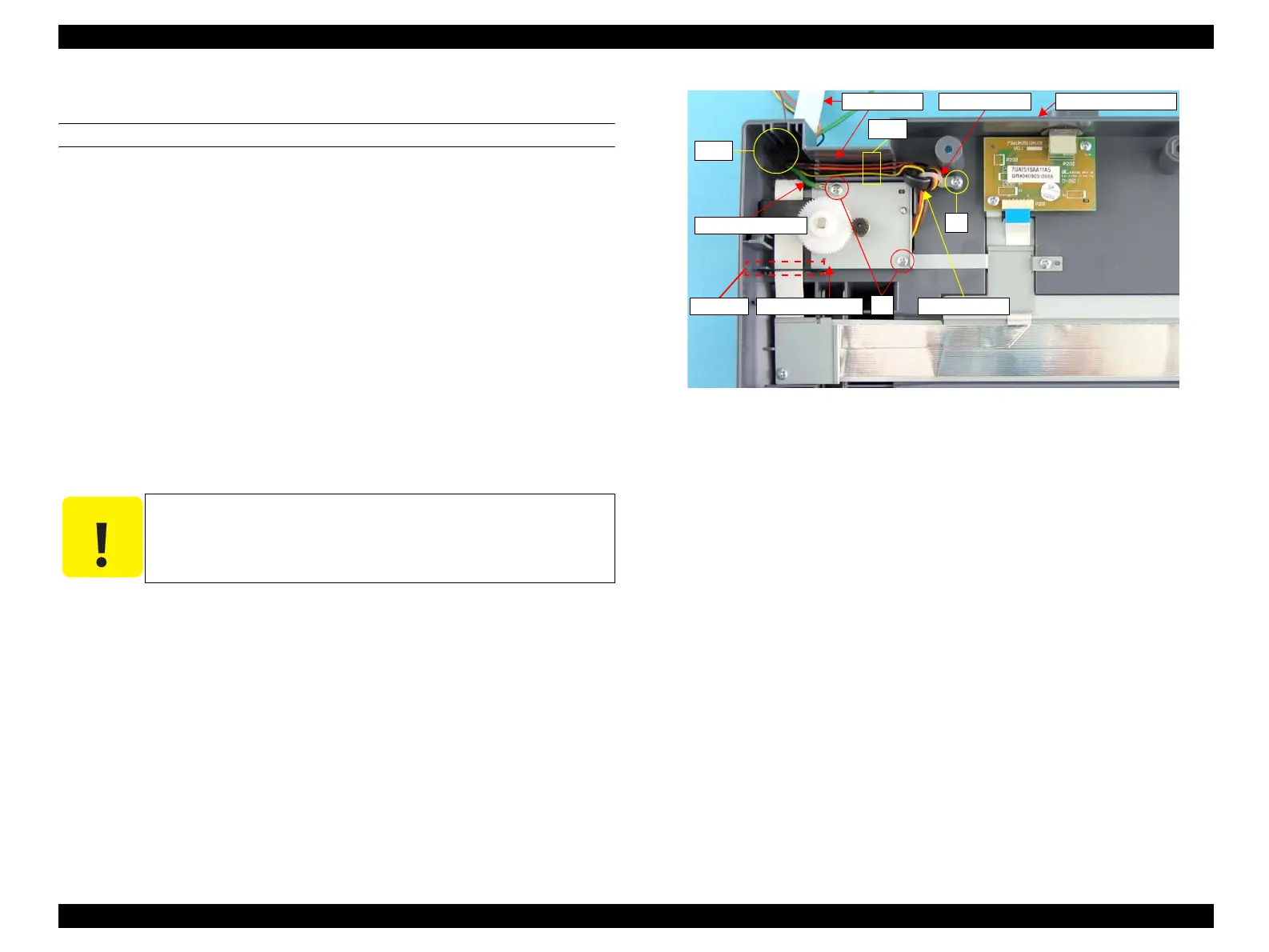
5. Pull the harnesses and the grounding wire of the MOTOR ASSY to the inner side
of the IR BASE A ASSY, and release the MOTOR ASSY harnesses from the
groove on the IR BASE A ASSY.
6. Remove the screw (M3 x 8 mm, P-type, B-head) that secure the harness tie.
7. Cut the harness tie, and remove the ferrite core from the harnesses.
8. Remove the two screws (M3 x 8 mm, P-type, B-head) that secure the MOTOR
ASSY to the IR BASE A ASSY, and remove the MOTOR ASSY from the IR
BASE A ASSY.
Figure 4-164. Removal of MOTOR ASSY
C A U T I O N
When removing/reinstalling the MOTOR ASSY, be careful not to
displace or remove the carriage home position detection flag.
5)-1
5)-2
6)
8)
Harnesses Harness Tie IR BASE A ASSY
Grounding Wire
MOTOR ASSY
Ferrite Core
HP Flag
 Loading...


