EPSON AcuLaser CX11/CX11F Revision B
DISASSEMBLY AND ASSEMBLY Printer 380
4.2.5.8 HOLDER-ADC 2ND
REMOVAL
1. Remove COVER ASSY RH.(p326)
2. Remove COVER FUSER. (p311)
3. Remove CHUTE ASSY-FSR and COVER ASSY-RR 2ND. (p366)
4. Remove 2ND BTR ASSY. (p374)
5. Remove PLATE BIAS-2ND.(p384)
6. Remove SENSOR 2BTR RETRACT. (p382)
7. Remove CAM ASSY-2ND. (p376)
8. Remove SPRING-2ND fastening both the left and right sides of FRAME ASSY-
2ND to the main unit. (p371)
9. Remove FUSER ASSY. (p415)
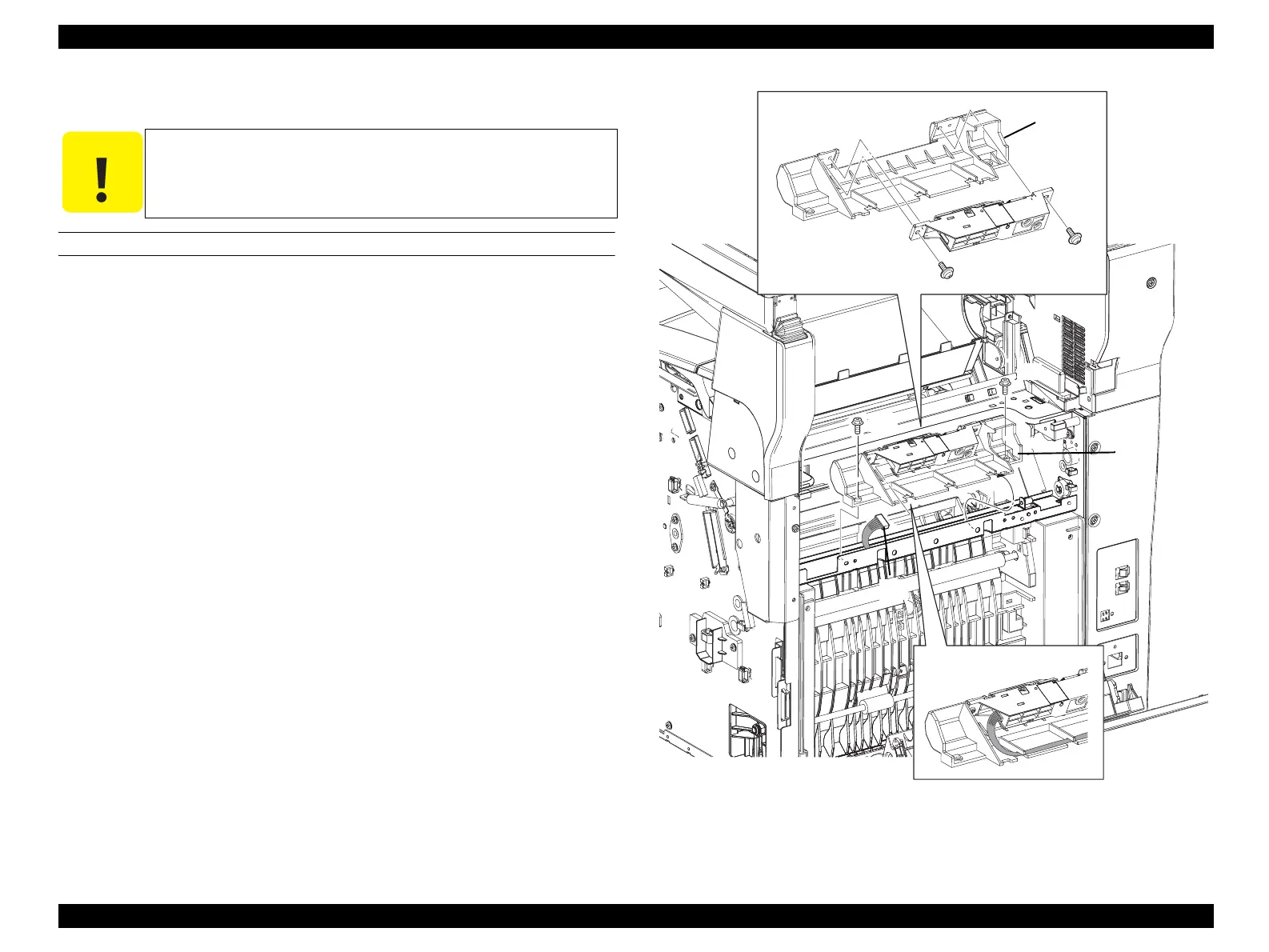
10. Disconnect connector (P/J431) from SENSOR ASSY ADC.
11. Remove the two screws (silver, with flange, 8 mm) that secure the HOLDER-ADC
2ND to the main unit.
12. Remove the HOLDER-ADC 2ND from the main unit together with the SENSOR ASSY
ADC.
13. Remove the two screws (silver with washer, tapping, 8 mm) that secure the SENSOR
ASSY ADC to the HOLDER-ADC 2ND.
14. Remove the SENSOR ASSY ADC from the HOLDER-ADC 2ND.
Figure 4-68. Removal of HOLDER-ADC 2ND
C A U T I O N
Step numbers with [ ] in the figure indicate the step of
reinstallation.
Leg_Sec03_512RA
14)
13)
13)
12)
[3)]
11)
11)
10)
manuals4you.commanuals4you.com
 Loading...


