EPSON AcuLaser CX11/CX11F Revision B
TROUBLESHOOTING Overview 129
3.1 Overview
For efficient troubleshooting, verify the condition of the trouble carefully using FIP
(Fault Isolation Procedures) with reference to
Chapter7 “Wiring Connection Diagrams”
(p.571)
and Chapter2 “OPERATING PRINCIPLES” (p.77).
3.1.1 Procedure for troubleshooting
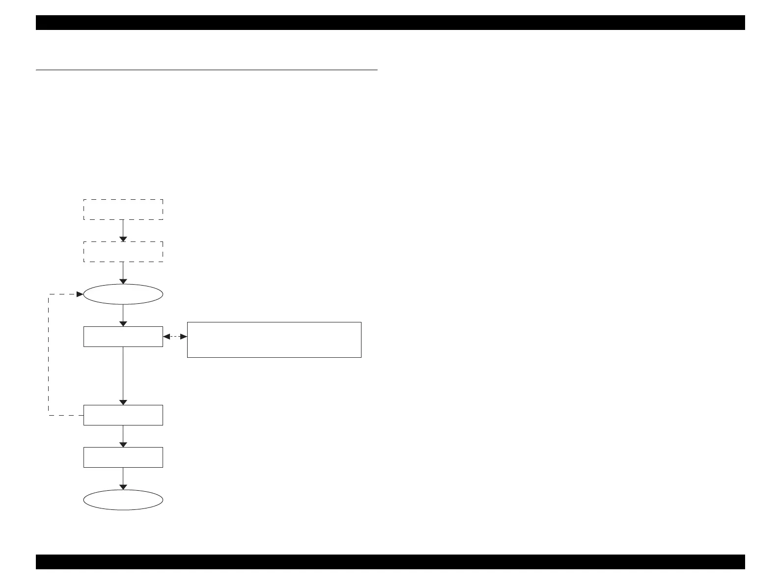
Perform troubleshooting work according to the following flowchart.
Figure 3-1. Procedure for troubleshooting
3.1.2 Checking Installation Status
Before starting troubleshooting, make sure that the following conditions are all met.
1. The power supply voltage must be within the specification limits. Measure the
voltage at the wall socket.)
2. The POWER CORD must be free from damage, short circuit or brokenage, or
miswiring in the POWER CORD.
3. The printer must be grounded properly.
4. The printer should not be located in a place where it can be exposed to too high or
low temperature, too high or low humidity, or abrupt temperature change.
5. The printer should not be located near waterworks, near humidifiers, near heaters
or near flames, in a dusty atmosphere, or in a place where the printer can be
exposed to air blasts from an air conditioner.
6. The printer should not be located in a place where volatile or inflammable gases
are produced.
7. The printer should not be located in a place where it can be exposed to direct
sunlight.
8. The printer must be located in a well-ventilated place.
9. The printer must be placed on a solid, stable and flat surface.
10. The paper used must conform to the specifications.
(Standard paper is recommended.)
11. There should be no errors in handling of the printer.
12. The Regular Replacement Parts must have been replaced every time their
respective specified number of sheets has been printed.
Verify the condition
of the trouble
Preliminary Check
Start
Execute FIP
Finish
Check if the trouble
returns to normal
Preventative
maintenance
* Clean the Feed Roller. And check if there is any
other part which is likely to cause another error.
Chapter2 “OPERATING PRINCIPLES” (p.77)
Chapter7 “Wiring Connection Diagrams” (p.571)
 Loading...


