EPSON AcuLaser CX11/CX11F Revision B
APPENDIX Printer System Electrical Connection 571
7.2.2 Wiring Connection Diagrams
7.2.2.1 Symbols used in the Overall Wiring Connection Diagram
The table below shows how to interpret the Overall Wiring Connection Diagrams.
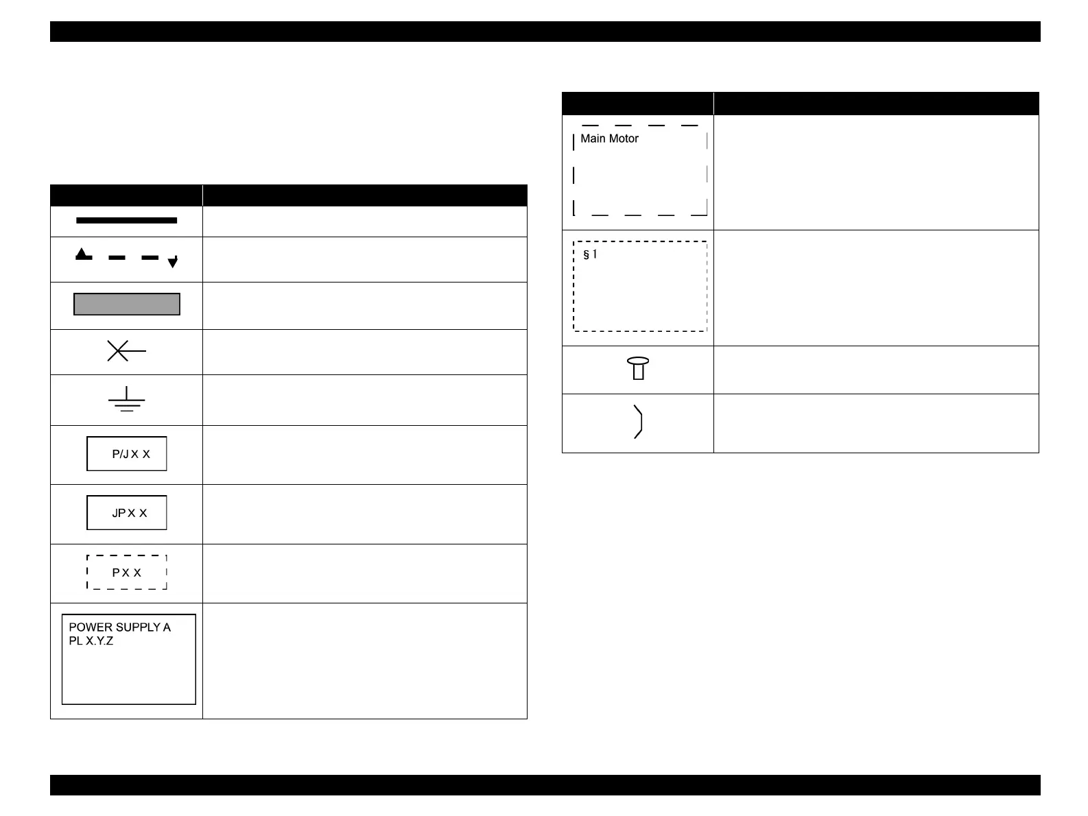
Table 7-3. List of the Symbols
Symbols Explanation
Indicates a connection between parts with a harness or wire.
Indicates a connection that differs according to the specification.
Indicates a connection between parts by conductive materials
such as a leaf spring.
Indicates a connection between parts with a screw.
Indicates Frame Ground.
Indicates a connector, and the connector No.
Indicates a connection terminal with a leaf spring or other spring
on a board, and the connector (terminal) No.
Indicates a connector attached directly to the board, and the
connector No.
Box with a part name in it indicates the part.
Indicates a functional component in a part, and its name.
Indicates a section in “7.2.3 Wiring Connection Diagram
between Parts (p573)”, and the section No.
Indicates a screw that secures conductive material such as a leaf
spring to harness.
Indicates conductive materials such as leaf spring.
Table 7-3. List of the Symbols
Symbols Explanation
 Loading...


