EPSON AcuLaser CX11/CX11F Revision B
DISASSEMBLY AND ASSEMBLY Printer 383
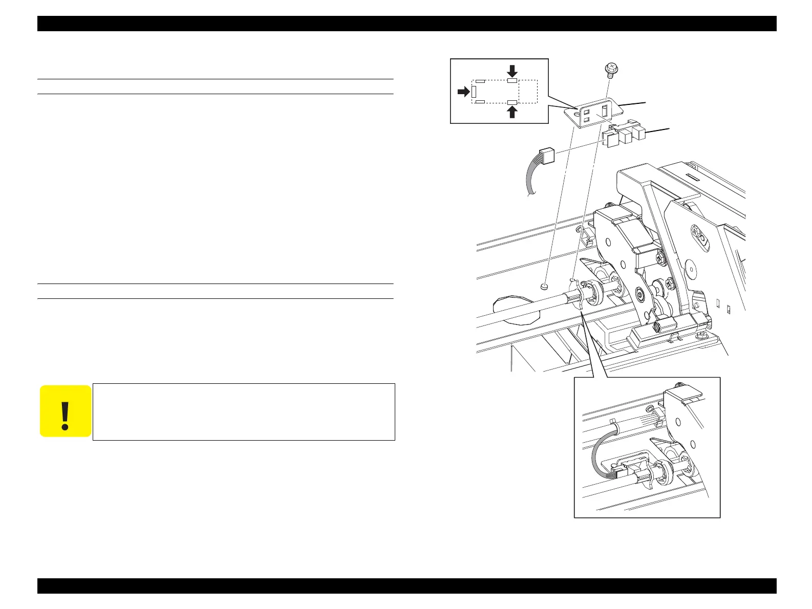
4.2.5.10 SENSOR IBT RETRACT
REMOVAL
1. Remove OP PANEL. (p320)
2. Remove COVER INNER TOP. (p324)
3. Disconnect connector (P/J107) from SENSOR IBT RETRACT.
4. Remove the screw (silver, with flange, 6 mm) fastening BRACKET-SENSOR
CLN to the main unit.
5. Remove BRACKET-SENSOR CLN from the main unit together with SENSOR
IBT RETRACT.
6. Unhook the three hooks fastening SENSOR IBT RETRACT to BRACKET-
SENSOR CLN, and remove SENSOR IBT RETRACT.
REINSTALLATION
1. Match the hooks on SENSOR IBT RETRACT with the attachment position, and
attach to BRACKET-SENSOR CLN.
2. Match the hole on BRACKET-SENSOR CLN with the boss on the main unit, and
attach BRACKET-SENSOR CLN together with SENSOR IBT RETRACT.
3. Fasten BRACKET-SENSOR CLN to the main unit with the screw (silver, with
flange, 6 mm).
4. Connect connector (P/J107) to SENSOR IBT RETRACT.
5. Attach COVER INNER TOP. (p324)
6. Attach OP PANEL. (p320)
Figure 4-70. Removal of SENSOR IBT RETRACT
C A U T I O N
The shutter of CAM ASSY-IBT CL must be inserted inside the
sensor on SENSOR IBT RETRACT.
Leg_Sec03_074FA
CAUTION
6)-1
3)
4)
5)
6)-2
 Loading...


