EPSON AcuLaser CX11/CX11F Revision B
DISASSEMBLY AND ASSEMBLY Printer 401
4.2.7 ROS
4.2.7.1 ROS ASSY
REMOVAL
1. Remove COVER ASSY RH. (p326)
2. Remove COVER ASSY LH. (p321)
3. Remove COVER MSI. (p317)
4. Remove COVER FRONT L and COVER FRONT ASSY U. (p318)
5. Remove COVER INNER LOWOW. (p327)
6. Remove FRAME ASSY-PH.(p352)
7. Remove CLEANER ASSY. (p403)
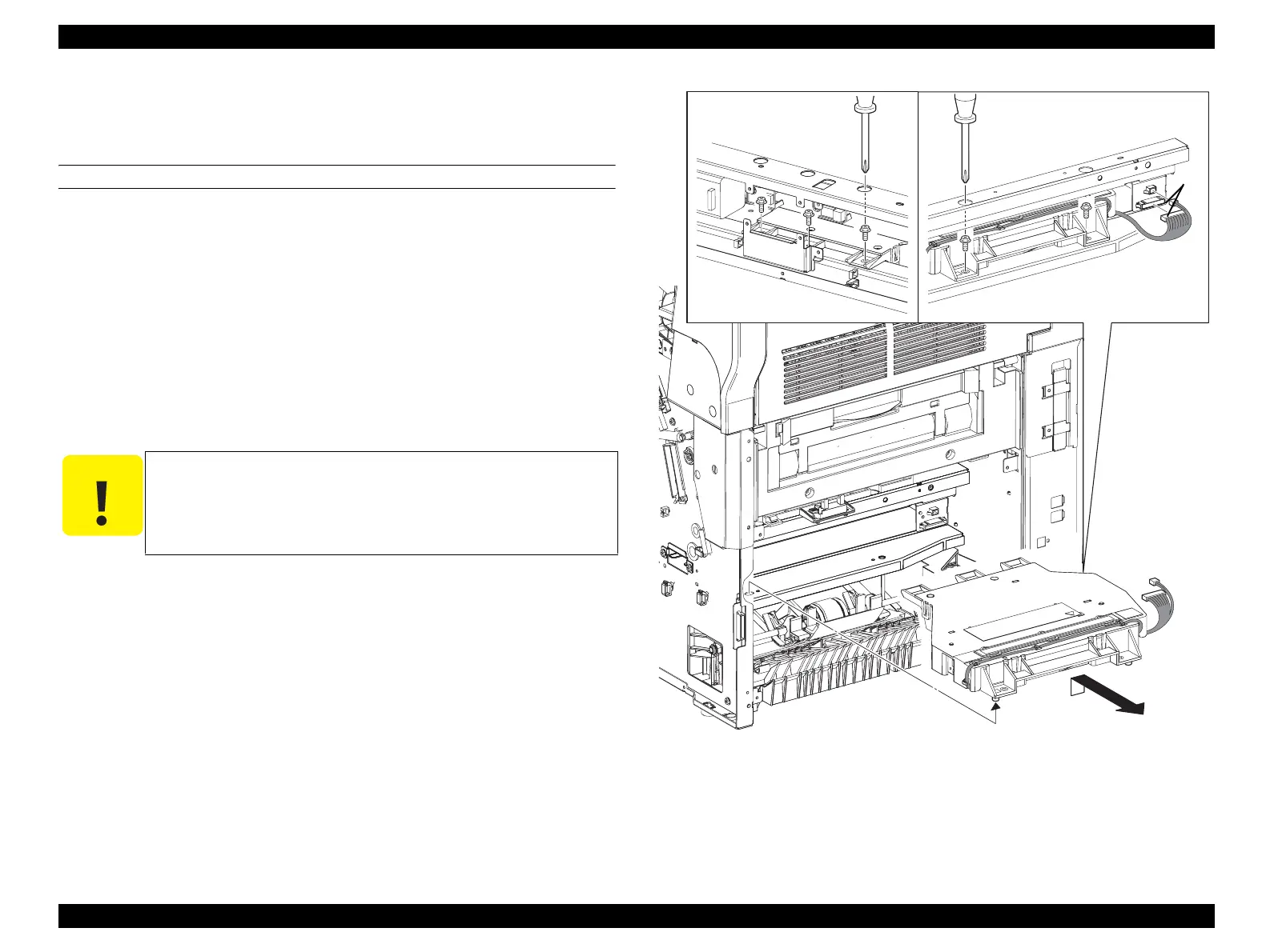
8. Disconnect P/J601 and P/J602 connectors of the ROS ASSY.
9. Remove the five screws (silver, with flange, 10 mm) that secure the ROS ASSY to
the main unit.
10. Lift the ROS ASSY a little to remove the boss of the assy. from the hole of the
main unit, and remove the ROS ASSY toward rear of the main unit.
Figure 4-87. Removal of ROS ASSY
C A U T I O N
When performing the subsequent procedures, be sure to perform
the followings to avoid touching the MAG ROLL; Unlock the
LATCH ROTARY of the LATCH ASSY-ROTARY and turn the
FRAME ASSY-ROTARY with your hand to move the Housing
ASSY-DEVE.
Leg_Sec03_086RC
FRONT REAR
9)
9)
8)
10)
 Loading...


