EPSON AcuLaser CX11/CX11F Revision B
DISASSEMBLY AND ASSEMBLY Scanner Section 482
4.3.2 COVER
4.3.2.1 IR COVER A ASSY
REMOVAL
1. Remove the Scanner. (p306)
2. Remove the ADF Unit. (p481)
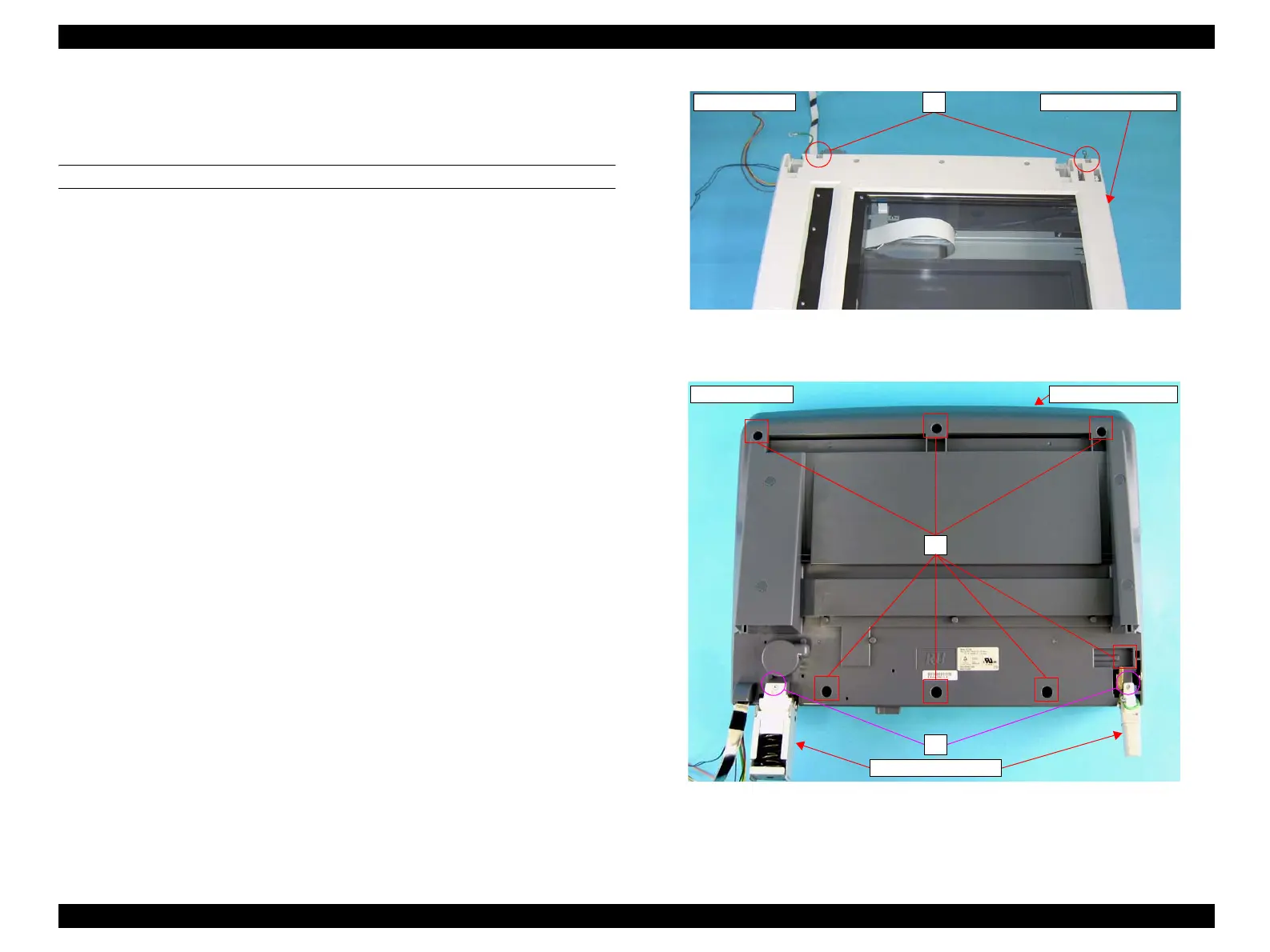
3. Remove the screw (M3 x 10 mm, P-type, B-head) that secure the both left and
right HINGE HOLDER 2s to the IR COVER A ASSY.
4. Turn the Scanner over and remove the two screws (M3 x 10 mm, P-type, B-head)
that secure the left and right HINNGE HOLDER 2s to the IR BASE A ASSY to
remove the two HINGE HOLDER 2s from the assy.
5. Remove the seven screws (M3 x 10 mm, P-type, B-head) that secure the IR
COVER A ASSY to the IR BASE A ASSY.
Figure 4-155. Removal of IR COVER A ASSY (1)
Figure 4-156. Removal of IR COVER A ASSY (2)
Obverse Side
3)
IR COVER A ASSY
Reverse Side IR BASE A ASSY
5)
4)
HINGE HOLDER 2
manuals4you.commanuals4you.com
 Loading...


