EPSON AcuLaser CX11/CX11F Revision B
DISASSEMBLY AND ASSEMBLY ADF Section 511
4.4.3.2 GUIDE FRONT ASSY
REMOVAL
1. Remove the Scanner. (p306)
2. Remove the ADF Unit. (p481)
3. Remove the ADF COVER R. (p492)
4. Remove the PAPER GUIDE ASSY. (p526)
5. Remove the ADF COVER C. (p496)
6. Remove the ADF BASE ASSY. (p498)
7. Remove the MOTOR. (p509)
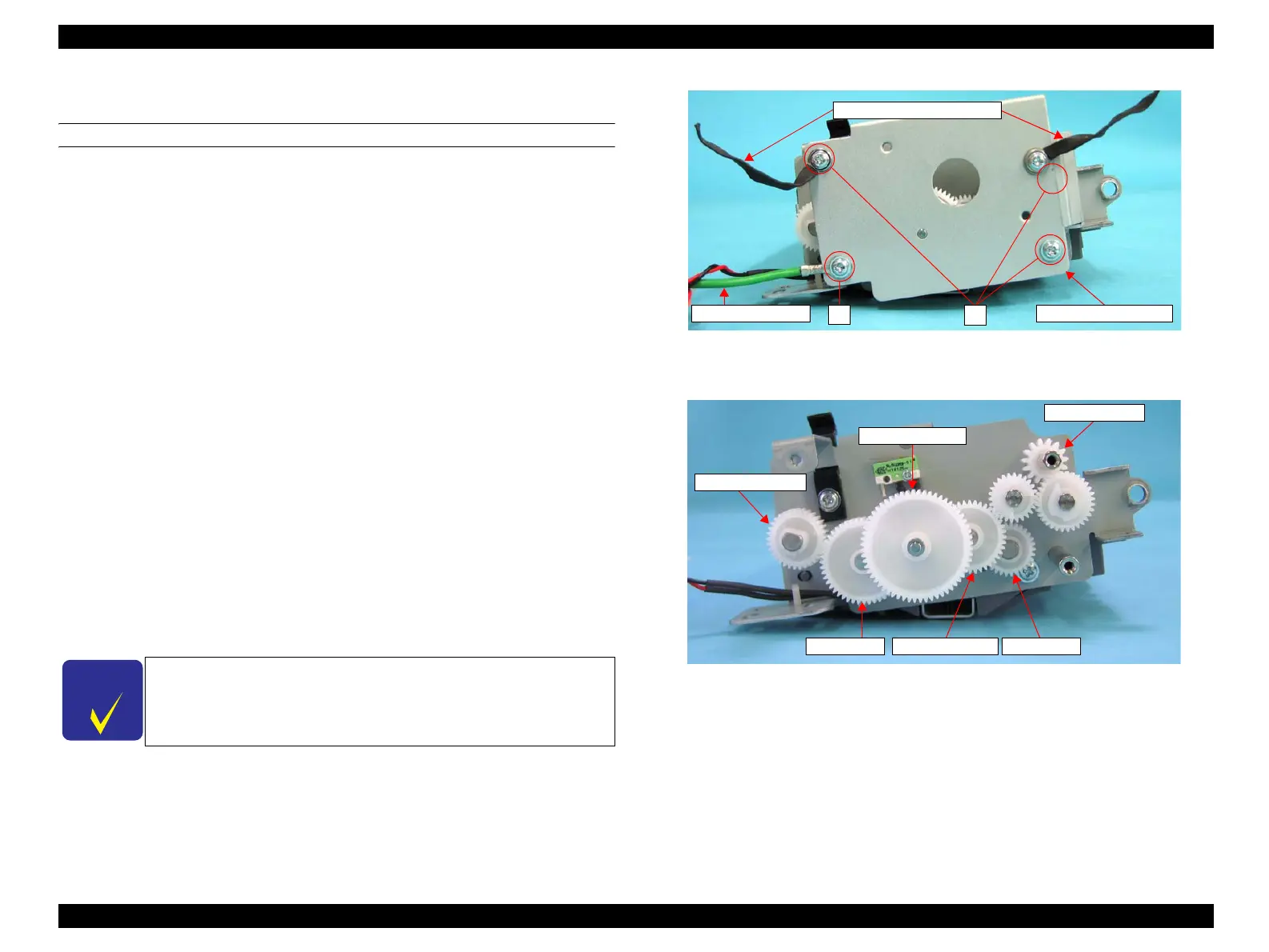
8. Remove the screw (M3 x 6 mm, S-type, A-head) that secures the grounding wire
of the CABLE to the MOTOR FIX PLATE, and remove the grounding wire of the
CABLE.
9. Remove the three screws (M3 x 6 mm, S-type, A-head) that secure the MOTOR
FIX PLATE to the FIX PLATE R, and remove the two LOCKING CABLE
CLIPs, and then remove the MOTOR FIX PLATE from the ADF BASE ASSY.
10. Remove the five gears attached on the FIX PLATE R in the order shown below.
1. GEAR 60T 18T
2. GEAR 48T
3. GEAR 40T 18T
4. GEAR 30T
5. GEAR 33T M0.5
Figure 4-198. Removal of GUIDE FRONT ASSY (1)
Figure 4-199. Removal of GUIDE FRONT ASSY (2)
C H E C K
P O I N T
GEAR 33T M0.5 is secured with a hook. When removing GEAR
33T M0.5, release it from the hook with a pair of tweezers or
similar tool.
Grounding Wire
9)
8)
LOCKING CABLE CLIPS
MOTOR FIX PLATE
GEAR 33T M0.5
GEAR 60T 18T
FIX PLATE R
GEAR 48T GEAR 40T 18T GEAR 30T
 Loading...


