EPSON AcuLaser CX11/CX11F Revision B
DISASSEMBLY AND ASSEMBLY ADF Section 509
4.4.3 ADF FRAME ASSY
4.4.3.1 MOTOR
REMOVAL
1. Remove the Scanner. (p306)
2. Remove the ADF Unit. (p481)
3. Remove the ADF COVER R. (p492)
4. Remove the PAPER GUIDE ASSY. (p526)
5. Remove the ADF COVER C. (p496)
6. Remove the ADF BASE ASSY. (p498)
7. Cut off the tie wrap that bundles the harnesses and the grounding wire of the
MOTOR.
8. Cut the tie wrap that secure the ferrite core to the harnesses of the MOTOR, and
remove the ferrite core from the harnesses.
9. Remove the two screws (M3 x 6 mm, S-type, A-head) that secure the MOTOR
CUSHION to the ADF FRAME ASSY, and remove the MOTOR CUSHION
together with the MOTOR. See Figure 4-195.
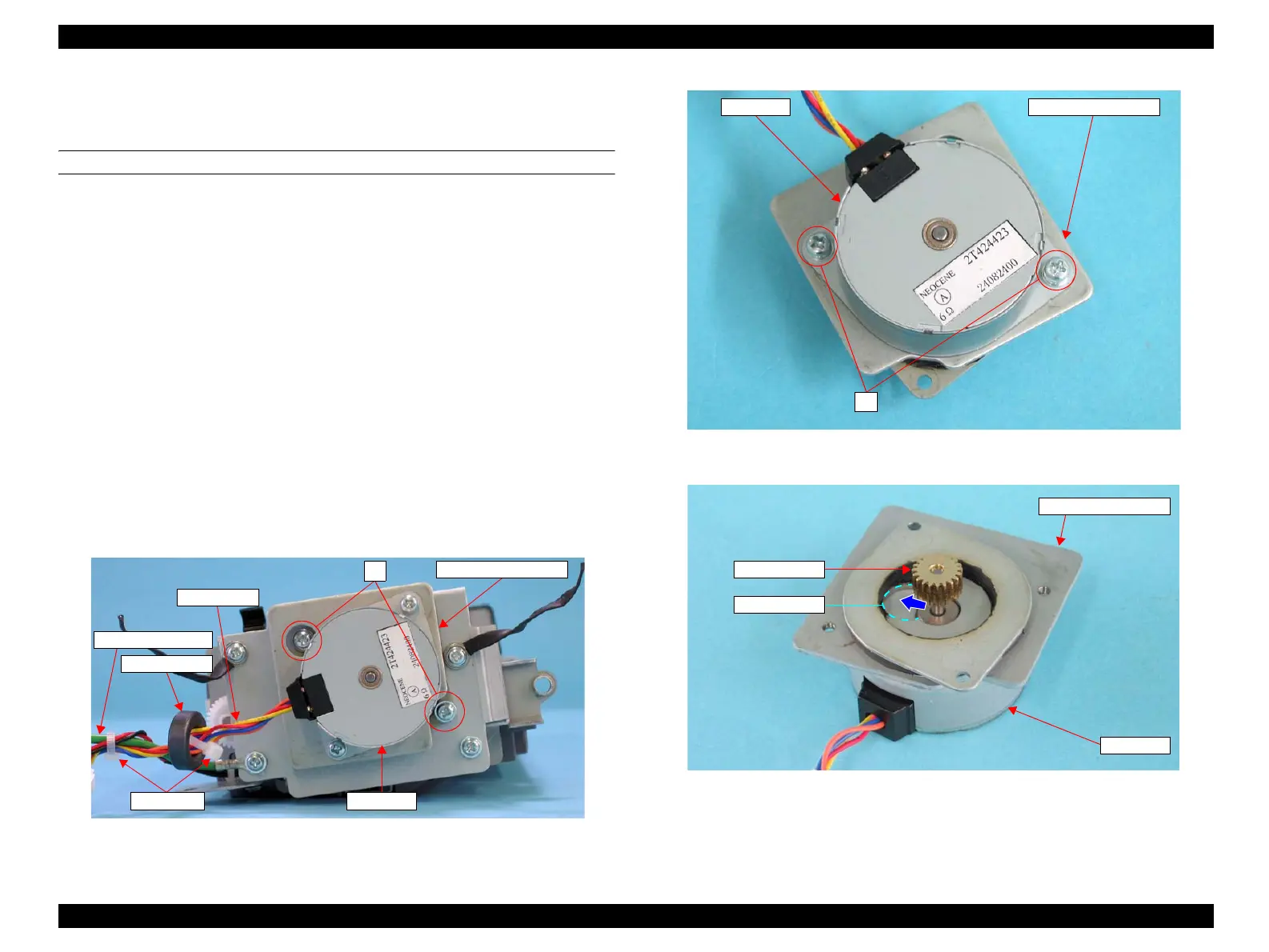
10. Remove the two screws (M3 x 6 mm, G-type, C-head, W/spring washer, Φ5 flat
washer) that secure the MOTOR to the MOTOR CUSHION. See Figure 4-196.
11. Move the MOTOR toward the relief hole on the MOTOR CUSHION, and remove
the MOTOR taking the pinion gear out through the hole. See Figure 4-197.
Figure 4-195. Removal of MOTOR (1)
Figure 4-196. Removal of MOTOR (2)
Figure 4-197. Removal of MOTOR (3)
Ferrite Core
Grounding Wire
Harnesses
7)
MOTOR CUSHION
Tie wrap MOTOR
MOTOR MOTOR CUSHION
8)
MOTOR
MOTOR CUSHION
Relief Hole
Pinion Gear
 Loading...


