EPSON AcuLaser CX11/CX11F Revision B
DISASSEMBLY AND ASSEMBLY Printer 419
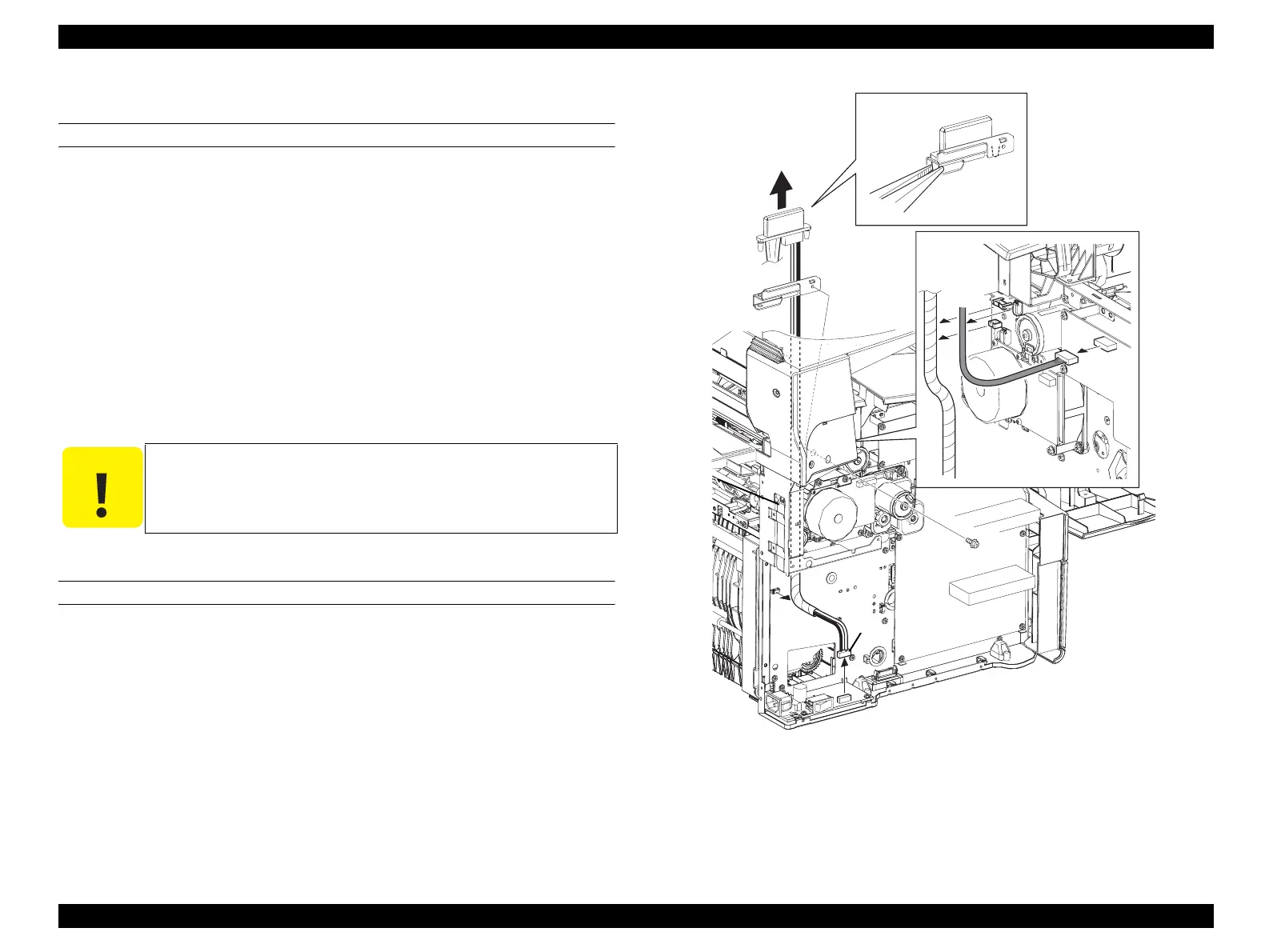
4.2.9.3 HARNESS ASSY MCU C/L
REMOVAL
1. Remove FUSER ASSY. (p415)
2. Remove COVER ASSY LH. (p321)
3. Remove CHASSIS ASSY ESS. (p440)
4. Disconnect the connector (black-and-white) from PWBA FUSER CONT.
5. Disconnect connector (P417) from PWBA MCU.
6. Remove the 2 screws (silver, with flange, 6 mm) fastening BRACKET-RIZ to the
main unit, remove the harness from the clamp, and remove BRACKET-RIZ from
the main unit.
7. Draw out HARNESS ASSY MCU C/L from BRACKET-RIZ while pressing the
claw on HARNESS ASSY MCU C/L.
REINSTALLATION
1. Insert the claw on HARNESS ASSY MCU C/L into the hole on BRACKET-RIZ
to attach.
2. Fasten BRACKET-RIZ to the main unit with the 2 screws (silver, with flange, 6
mm), and fasten each harness with the clamps.
3. Attach the harness (yellow) to the connector (P417) on PWBA MCU.
4. Connect the harness (black-and-white) to PWBA FUSER CONT.
5. Attach CHASSIS ASSY ESS. (p440)
6. Attach COVER ASSY LH. (p321)
7. Attach FUSER ASSY. (p415)
Figure 4-102. Removal of HARNESS ASSY MCU C/L
C A U T I O N
The claw on HARNESS ASSY MCU C/L is easily broken. Take
care not to press it too much.
Leg_Sec03_520RB
7)-1
7)-2
6)-2
5)
6)-1
6)-2
4)
 Loading...


