EPSON AcuLaser CX11/CX11F Revision B
DISASSEMBLY AND ASSEMBLY Printer 390
4.2.6.3 LATCH ASSY D
REMOVAL
1. Remove 2ND BTR ASSY. (p374)
2. Remove COVER ASSY LH. (p321)
3. Remove PWBA MCU. (p432)
4. Remove CHASSIS ASSY ESS. (p440)
5. Remove SENSOR TR-0. (p387)
6. Remove GUIDE CRU ASSY D. (p388)
7. Remove ANTENNA ASSY. (p391)
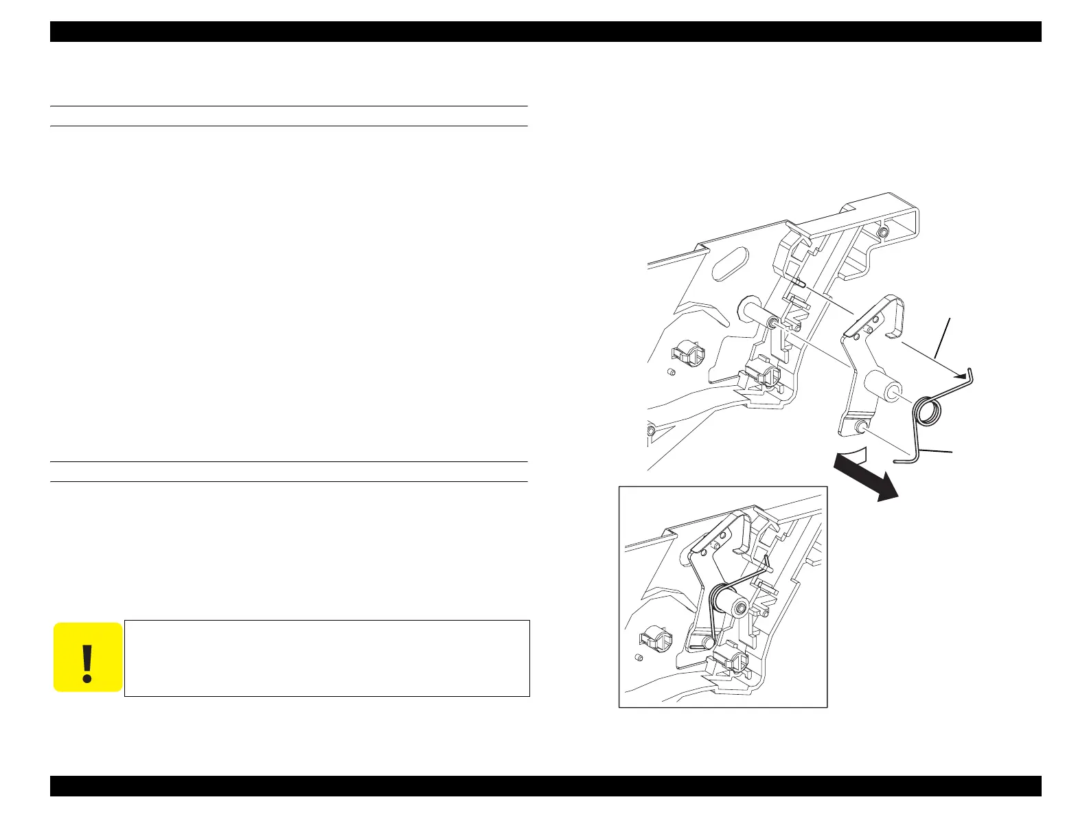
8. Unhook SPRING-TORSION D from the hook on GUIDE CRU ASSY D.
9. Slightly rotate LATCH ASSY D together with SPRING-TORSION D in the
direction of the arrow so that they escape the notch on GUIDE CRU ASSY D to
remove.
10. Remove SPRING-TORSION D from LATCH ASSY D.
REINSTALLATION
1. Attach SPRING-TORSION D to LATCH ASSY D.
2. Attach LATCH ASSY D to GUIDE CRU ASSY D together with SPRING-
TORSION D, and insert the bottom front side of LATCH ASSY D into the notch
on GUIDE CRU ASSY D.
3. Hook SPRING-TORSION D onto the hook on GUIDE CRU ASSY D.
4. Attach ANTENNA ASSY. (p391)
5. Attach GUIDE CRU ASSY D. (p388)
6. Attach SENSOR TR-0. (p387)
7. Attach CHASSIS ASSY ESS. (p440)
8. Attach PWBA MCU. (p432)
9. Attach COVER ASSY LH. (p321)
10. Attach 2ND BTR ASSY. (p374)
Figure 4-76. Removal of LATCH ASSY D
C A U T I O N
SPRING-TORSION D must be firmly attached onto the hooks on
LATCH ASSY D and GUIDE CRU ASSY D.
Leg_Sec03_201FA
CAUTION
8)
10)
9)
manuals4you.commanuals4you.com
 Loading...


