EPSON AcuLaser CX11/CX11F Revision B
APPENDIX Printer System Electrical Connection 579
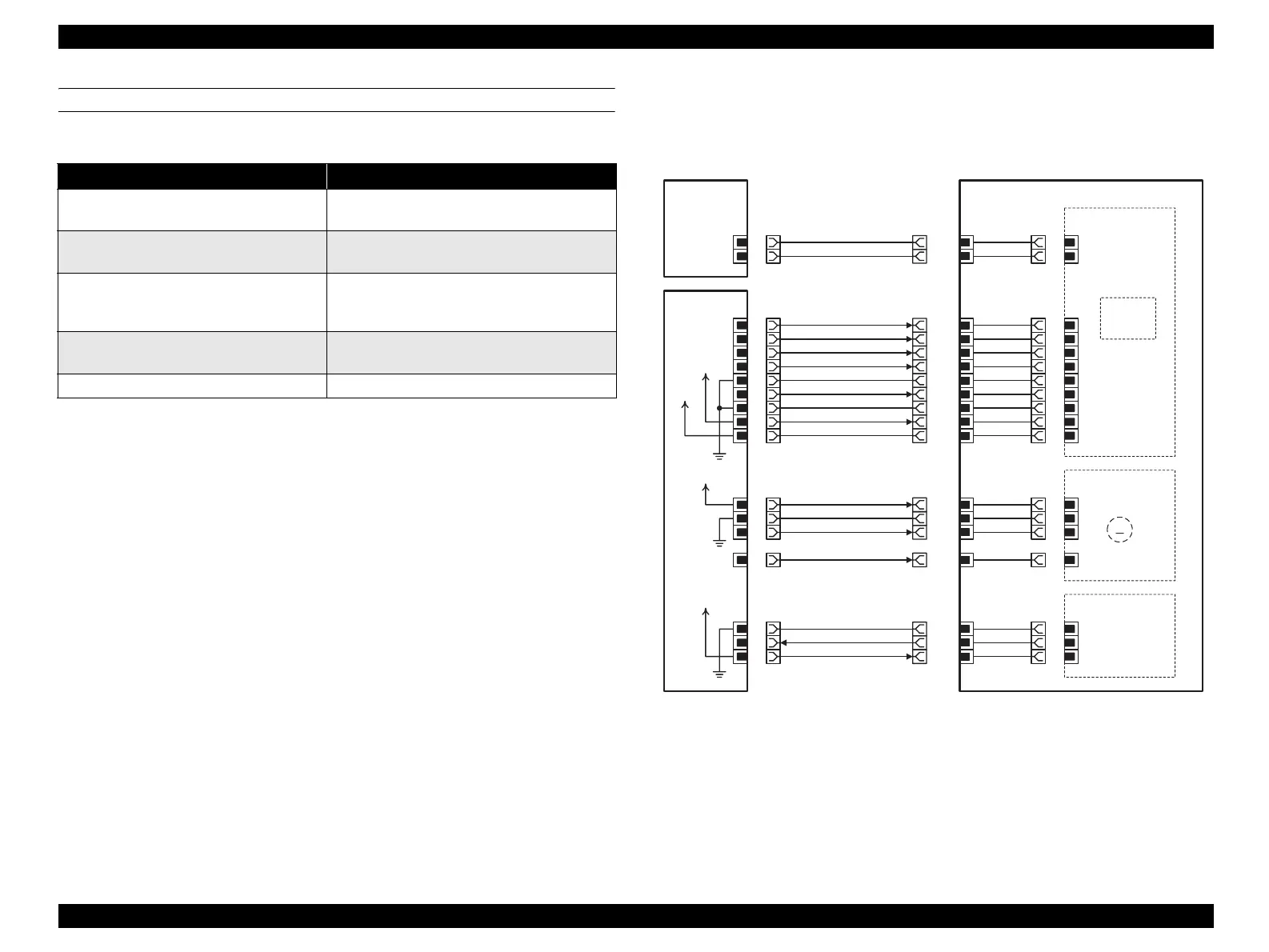
4. ROS
Figure 7-11. ROS Connection and Wiring Diagram
Name of Signal Line Remarks
ESS DATA-
ESS DATA+
Image signal from ESS
MCU DATA-
MCU DATA+
Image signal from MCU
PCONT
LASER ON (L) +5VDC
VREF
PWBA LD control signal in ROS ASSY
SCANNER MOTOR ON (L) +5VDC
SCANNER MOTOR CLOCK
PWBA Scanner control signal in ROS ASSY
SOS SENSED (L) +5VDC
Reference signal for start of laser scanning
SOS PWB
SCANNER PWB
SCANNER MOTOR
PWBA LD
PWBA ESS
PL12.2.7
CN602
1
2
P/J407
1
2
3
4
5
6
7
8
9
10
11
12
13
14
15
16
P/J424
9
8
7
6
5
4
3
2
1
P/J425
5
4
3
1
P/J426
3
2
1
PWBA MCU
PL12.2.1
P/J602
2
1
P/J601
16
15
14
13
12
11
10
9
8
7
6
5
4
3
2
1
1
1
2
2
3
4
5
6
7
8
9
10
11
12
13
14
15
16
P/J427
2
1
DATA-
DATA+
DATA-
DATA+
P CONT
LASER ON (L) +5VDC
SG
VREF
SG
+5VDC
+3.3VDC
I/L +24VDC
SG
SCAN MOT ON(L) +5VDC
SCAN MOT CLOCK
SG
SOS SENSED (L) +5VDC
+5VDC
ROS ASSY
PL8.1.1
Single
Beam Laser
Diode
M
INTERLOCK
+24VDC
+5VDC
+3.3VDC
+5VDC
Leg_007_005RA
 Loading...


