EPSON AcuLaser CX11/CX11F Revision B
DISASSEMBLY AND ASSEMBLY Printer 428
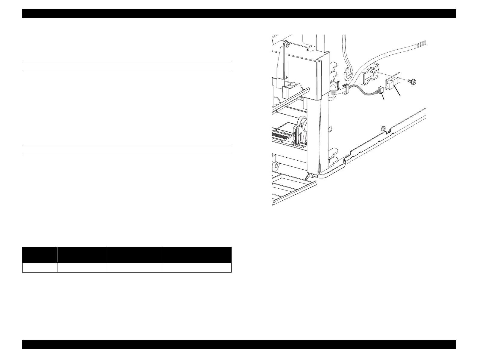
4.2.11 ELECTRICAL
4.2.11.1 SENSOR HUM & TEMP
REMOVAL
1. Remove COVER ASSY RH. (p326)
2. Disconnect connector (P/J104) from SENSOR HUM & TEMP.
3. Remove the screw (silver, with flange, tapping, 8 mm) fastening SENSOR HUM
& TEMP to the main unit.
4. Remove SENSOR HUM & TEMP from the main unit.
REINSTALLATION
1. Attach SENSOR HUM & TEMP to the main unit.
2. Fasten SENSOR HUM & TEMP to the main unit with the screw (silver, with
flange, tapping, 8 mm).
3. Connect the connector (P/J104) to SENSOR HUM & TEMP.
4. Attach COVER ASSY RH. (p326)
Figure 4-110. Removal of SENSOR HUM & TEMP
Table 4-11. Symptoms when the connector is loose
Connector
No.
Panel Indication Symptom
Error Caused by Connector
Disconnection
P/J104 Service Req E533 All LEDs flash
Sensor HUM & TEMP error
Leg_Sec03_107EA
3)
4)
2)
manuals4you.commanuals4you.com
 Loading...


