EPSON AcuLaser CX11/CX11F Revision B
DISASSEMBLY AND ASSEMBLY Printer 367
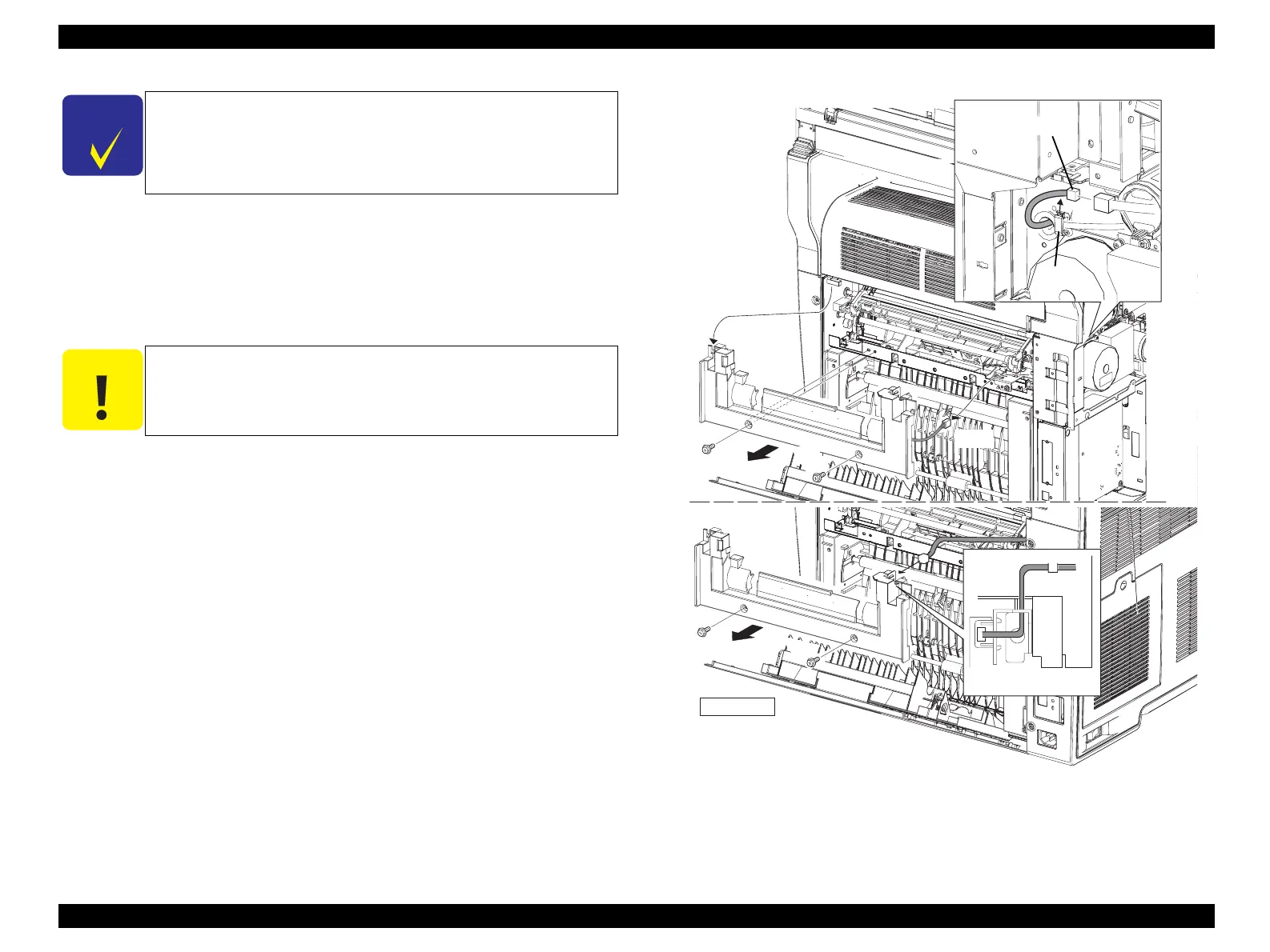
COVER ASSY-RR 2ND
4. Remove COVER ASSY LH. (p321)
5. Unclamp the clamp fastening the harness of COVER ASSY-RR 2ND, and remove
the harness.
6. Disconnect connector (P/J621) connected to the main unit, and insert the
connector inside through the hole on the main unit.
7. Remove the 2 screws (silver, with flange, 8 mm) fastening COVER ASSY-RR
2ND to the main unit.
8. Remove COVER ASSY-RR 2ND from the main unit.
Figure 4-59. Removal of COVER ASSY-RR 2ND
C H E C K
P O I N T
When HARNESS ASSY 2BTR SW need not be removed in the
following procedure, COVER ASSY-RR 2ND can be removed
without removing COVER ASSY LH by disconnecting connector
(P/J113) from SWITCH 2BTR COVER instead of connector (P/
J621).
C A U T I O N
When performing the following work, leave the intermediate
connector on the harness side.
Leg_Sec03_143RB
CHECK POINT
6)-2
6)-1
7)
8)
5)
7)
 Loading...


