EPSON AcuLaser CX11/CX11F Revision B
DISASSEMBLY AND ASSEMBLY Printer 421
4.2.10.2 DRIVE ASSY PRO
REMOVAL
1. Remove COVER ASSY LH. (p321)
2. Remove OP PANEL. (p320)
3. Remove COVER INNER TOP. (p324)
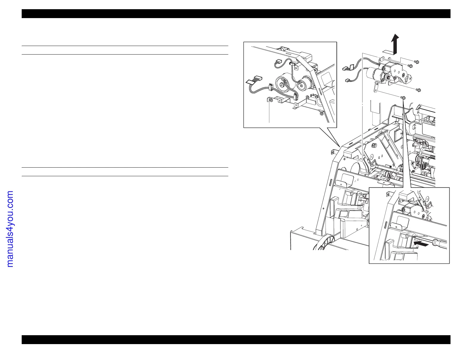
4. Disconnect connector (P/J411,P/J414) from the PWBA MCU.
5. Unclamp the harness on DRIVE ASSY PRO on the left side of the main unit from
the clamp. If the harness is difficult to remove, remove PWBA MCU. (p432)
6. Remove the 4 screws (silver, with flange, 6 mm) fastening DRIVE ASSY PRO to
the main unit.
7. Remove DRIVE ASSY PRO from the main unit.
REINSTALLATION
1. Inset the motor section and harness on DRIVE ASSY PRO into the hole on the
main unit, match the hole on DRIVE ASSY PRO with the boss on the main unit,
and attach DRIVE ASSY PRO.
2. Fasten DRIVE ASSY PRO to the main unit with the 4 screws (silver, with flange,
6 mm).
3. Fasten the harness on DRIVE ASSY PRO with the clamp on the left side of the
main unit.
4. Connect connector (P/J411,P/J414) to the PWBA MCU.
5. Attach COVER INNER TOP. (p324)
6. Attach OP PANEL. (p320)
7. Attach COVER ASSY LH. (p321)
Figure 4-104. Removal of DRIVE ASSY PRO
Leg_Sec03_099EA
5)
7)
6)
6)
6)
6)
manuals4you.com
 Loading...


