EPSON AcuLaser CX11/CX11F Revision B
DISASSEMBLY AND ASSEMBLY Printer 323
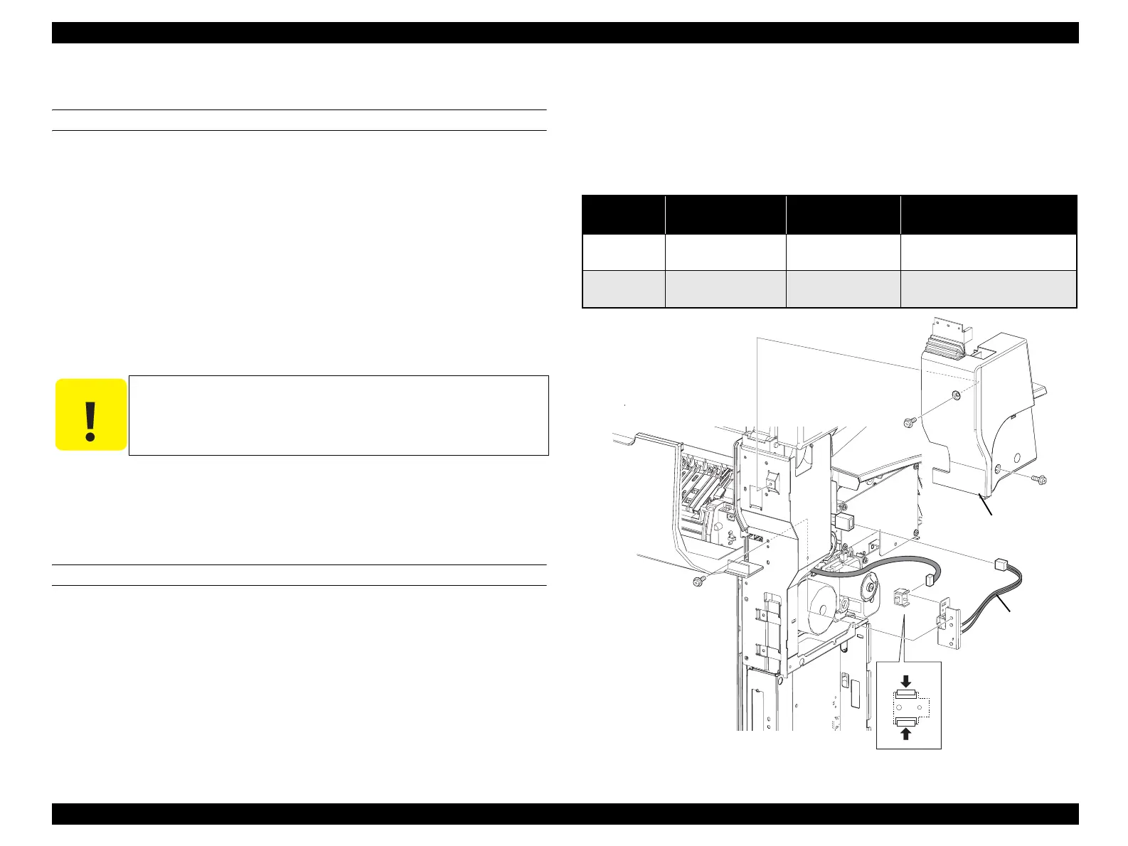
4.2.2.14 SWITCH ASSY FUSER, SWITCH-FUSER DOOR
REMOVAL
1. Remove COVER ASSY LH. (p321)
2. Open COVER FUSER.
3. Remove the two screws (silver, with flange, 8mm) that secure the COVER LEG
LH OUTER to the main unit, and remove the COVER LEG LH OUTER from the
main unit together with the HINGE COVER L.
4. Unclamp clamp fastening the harness of SWITCH ASSY FUSER and remove the
harness.
5. Remove the screw (silver, with flange, 8 mm) fastening SWITCH ASSY FUSER
to the main unit.
6. Remove SWITCH ASSY FUSER from the main unit.
7. Disconnect the connector (P/J117, blue) from the SWITCH ASSY FUSER.
8. Unhook the two hooks fastening the SWITCH-FUSER DOOR to BRACKET SW
FUSER, and remove the SWITCH-FUSER DOOR.
9. Disconnect the connector (P/J114) from the SWITCH-FUSER DOOR.
EINSTALLATION
1. Connect the connector (P/J114) to the SWITCH-FUSER DOOR.
2. Match the hooks on the SWITCH-FUSER DOOR with the attachment position,
and attach to the BRACKET SW FUSER.
3. Connect the connector (P/J117, blue) to the SWITCH ASSY FUSER.
4. Match the hole on the SWITCH ASSY FUSER with the boss on the main unit.
5. Fasten the SWITCH ASSY FUSER to the main unit with the screw (silver, with
flange, 8 mm).
6. Fasten the harness of the SWITCH ASSY FUSER with the clamp.
7. Secure the COVER LEG LH OUTER with the two screws (silver, with flange, 8
mm) to the main unit together with the HINGE COVER L.
8. Close the COVER FUSER.
9.
Attach COVER ASSY LH.
(p321)
Figure 4-18. Removal of SWITCH ASSY FUSER and SWITCH-FUSER DOOR
C A U T I O N
When performing the following work, leave the intermediate
connector on the harness side.
Table 4-5. Symptoms when the connector is loose
Connector No. Panel Indication Symptom
Error Caused by Connector
Disconnection
P/J114 C Open
Printing is not
possible.
---
P/J117 C Open
Printing is not
possible.
---
Leg_Sec03_012RB
7)
3)-1
3)-1
3)-2
8)-2
5)
8)-1
9)
6)
7)
 Loading...


