EPSON AcuLaser CX11/CX11F Revision B
DISASSEMBLY AND ASSEMBLY Printer 320
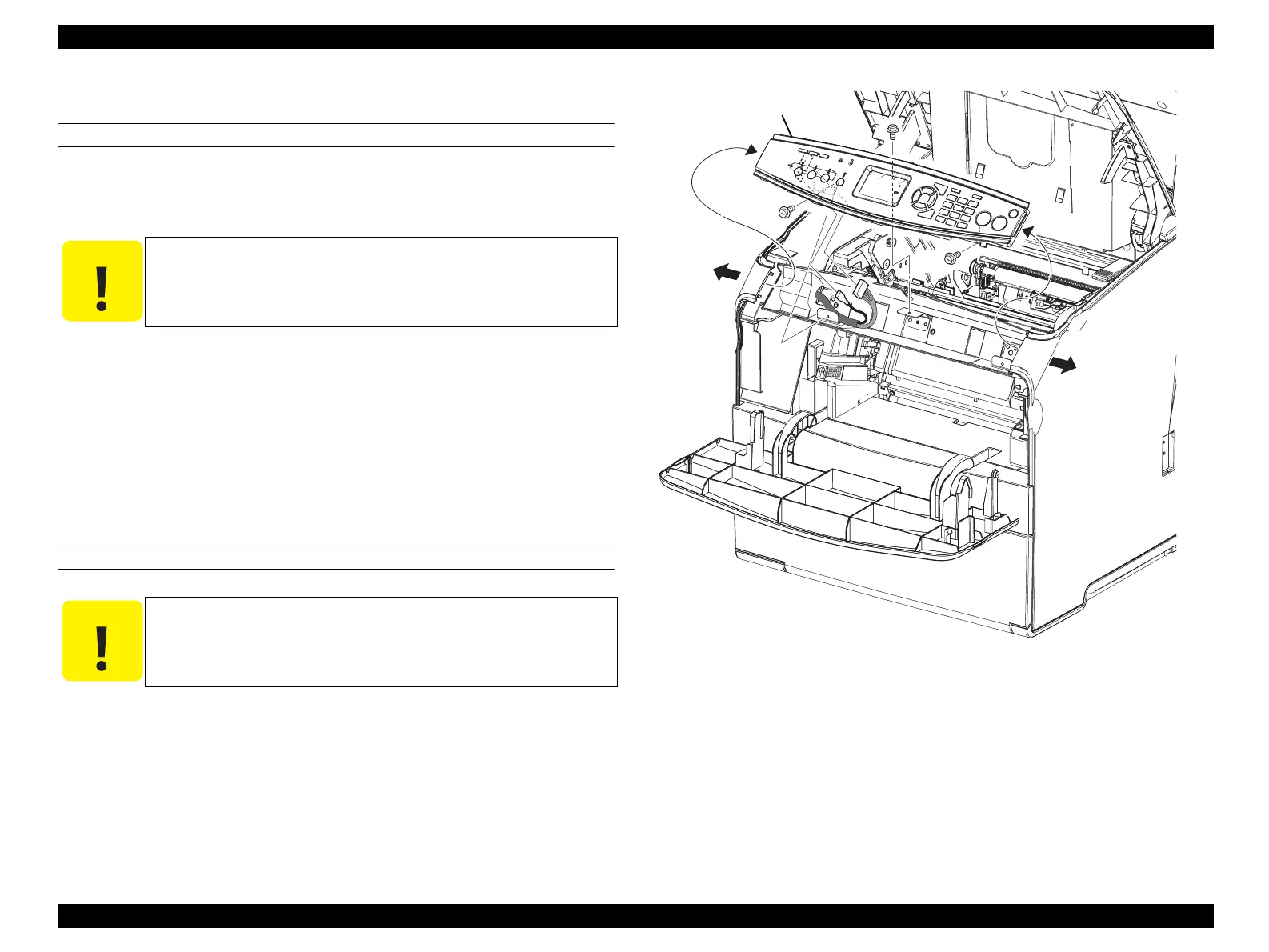
4.2.2.11 OP PANEL (CONTROL, PANEL)
REMOVAL
1. Open COVER ASSY TOP.
2. Open COVER FRONT ASSY U.
3. Remove the 3 screws (silver, with flange, 6 mm) fastening OP PANEL to the main
unit.
4. Remove the protrusions on the left and right of OP PANEL from COVER RH and
COVER LH while pushing them outward, and slightly remove OP PANEL from
the main unit.
5. Disconnect connector CN1 and the terminal connected to OP PANEL to remove
OP PANEL.
REINSTALLATION
1. Connect connector CN1 and the terminal to OP PANEL.
2. While extending COVER RH and COVER LH each to the left and right, put the
protrusions on the left and right of OP PANEL inside COVER RH and COVER
LH, and attach OP PANEL to the main unit.
3. Fasten OP PANEL to the main unit with the 3 screws (silver, with flange, 6 mm).
4. Close COVER FRONT ASSY U.
5. Close COVER ASSY TOP.
Figure 4-15. Removal of OP PANEL
C A U T I O N
When performing the following work, take care not to remove OP
PANEL too far as it is connected by a harness.
C A U T I O N
When performing the following work, take care to prevent the
harness from being caught between the main unit and OP PANEL.
Leg_Sec03_184RB
4)-1
4)-1
3)
3)
3)
4)-2
manuals4you.commanuals4you.com
 Loading...


