EPSON AcuLaser CX11/CX11F Revision B
DISASSEMBLY AND ASSEMBLY Printer 397
4.2.6.7 CAP-PLATE PR, PLATE-ASSY PR
REMOVAL
1. Remove COVER ASSY RH. (p326)
2. Remove 2ND BTR ASSY. (p374)
3. Remove FRAME ASSY-PH. (p352)
4. Remove BCR CLN XERO ASSY. (p399)
5. Remove SENSOR TR-0. (p387)
6. Remove GUIDE CRU ASSY AD. (p393)
7. Remove LEVER-LATCH PR. (p396)
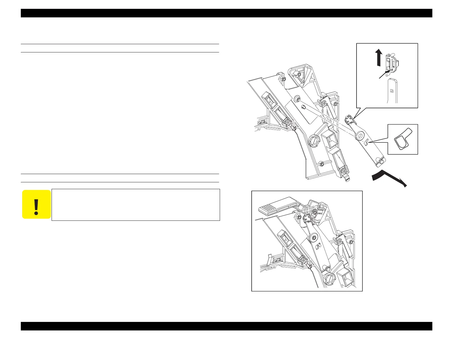
8. Turn PLATE-ASSY PR in the direction of the arrow, match the notch on PLATE-
ASSY PR with the protrusion on GUIDE CRU ASSY AD, and remove PLATE-
ASSY PR together with CAP-PLATE PR.
9. Unhook the hook on CAP-PLATE PR, and remove CAP-PLATE PR from
PLATE-ASSY PR.
REINSTALLATION
1. Attach CAP-PLATE PR to PLATE-ASSY PR.
2. Match the notch on PLATE-ASSY PR with the protrusion on GUIDE CRU ASSY
AD, and attach PLATE-ASSY PR together with CAP-PLATE PR.
3. Attach LEVER-LATCH PR. (p396)
4. Attach GUIDE CRU ASSY AD. (p393)
5. Attach SENSOR TR-0. (p387)
6. Attach BCR CLN XERO ASSY. (p399)
7. Attach FRAME ASSY-PH. (p352)
8. Attach 2ND BTR ASSY. (p374)
9. Attach COVER ASSY RH. (p326)
Figure 4-83. Removal of CAP-PLATE PR and PLATE-ASSY PR
C A U T I O N
When performing the following work, pay attention to the
attachment direction of CAP-PLATE PR.
Leg_Sec03_203FA
8)
9)-2
9)-1
 Loading...


