EPSON AcuLaser CX11/CX11F Revision B
DISASSEMBLY AND ASSEMBLY Printer 326
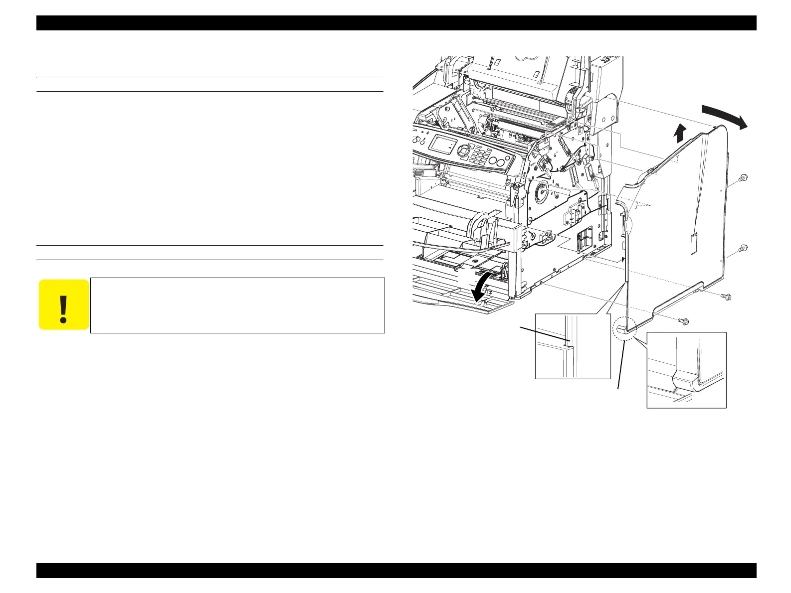
4.2.2.17 COVER ASSY RH
REMOVAL
1. Open COVER ASSY TOP.
2. Open COVER FRONT ASSY U.
3. Open COVER MSI.
4. Remove the 4 screws (silver, with flange, 8 mm) fastening the COVER ASSY RH
to the main unit.
5. Lift up the COVER ASSY RH, and unhook the 4 hooks on the rear of the COVER
ASSY RH from the holes on the main unit, and remove the COVER ASSY RH.
REINSTALLATION
1. While inserting the protrusion on the COVER ASSY RH into the concave portion
on the COVER FRONT L, place the "A" section of the COVER ASSY RH under
the COVER FRONT L as shown in Figure 4-21, and attach the COVER ASSY RH
to the COVER FRONT L with four tabs.
2. Secure the COVER ASSY RH with the four screws (silver, with flange, 8mm).
3. Close COVER MSI.
4. Close COVER FRONT ASSY U.
5. Close COVER ASSY TOP.
Figure 4-21. Removal of COVER ASSY RH
C A U T I O N
When performing the following work, be sure to insert the
protrusion on the front side of the COVER ASSY RH into the
concave portion on the COVER FRONT L.
Leg_Sec03_185RB
CAUTION
3)
5)-1
5)-2
4)
4)
4)
4)
Section A
Protrusion
manuals4you.commanuals4you.com
 Loading...


