EPSON AcuLaser CX11/CX11F Revision B
DISASSEMBLY AND ASSEMBLY Printer 387
4.2.6 XERO
4.2.6.1 SENSOR TR-0
REMOVAL
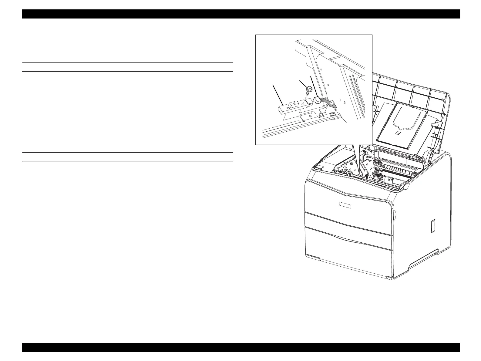
1. Open COVER ASSY TOP.
2. Remove Photoconductor Unit.
3. Remove the screw (silver, with flange, 10mm) fastening SENSOR TR-0 to
PLATE-TR-0.
4. Remove SENSOR TR-0 from PLATE-TR-0.
5. Disconnect connector (P/J108) from SENSOR TR-0.
REINSTALLATION
1. Connect connector (P/J108) to SENSOR TR-0.
2. Match the hole on SENSOR TR-0 with the boss on PLATE-TR-0, and attach
SENSOR TR-0.
3. Fasten SENSOR TR-0 to PLATE-TR-0 with the screw (silver, with flange,
10mm).
4. Attach Photoconductor Unit.
5. Close COVER ASSY TOP.
Figure 4-73. Removal of SENSOR TR-0
Leg_Sec03_076EA
4)
3)
5)
 Loading...


