EPSON AcuLaser CX11/CX11F Revision B
DISASSEMBLY AND ASSEMBLY Overview 305
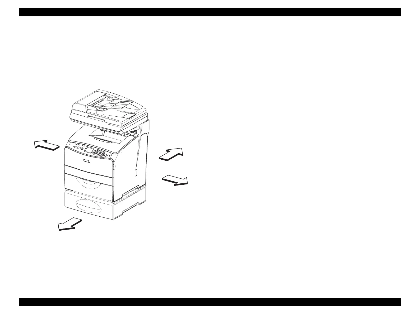
4.1.5 Conventions used in descriptions of procedures
Expressions relating to directions in procedures are defined as follows:
FRONT : Front direction facing the front side of the printer
REAR : Rear direction facing the front side of the printer
LEFT : Left direction facing the front side of the printer
RIGHT : Right direction facing the front side of the printer
Figure 4-1. Definition of Printer Orientation
Sections in procedures described as “In the case of the … specification” refer to
work to be performed on printers of a specific specification. (Work is not to be
performed on printers that do not fall under this specification.)
Screws in illustrations are to be loosened and removed using a Phillips screwdriver
unless otherwise specified.
Black arrows in illustrations indicate that the part should be moved in the indicated
direction.
When black arrows are given a consecutive number, this indicates that they should
be moved in the indicated order.
For details on positions of connectors (P/J), refer to “APPENDIX” (p564)
REAR
FRONT
LEFT
RIGHT
Leg_Sec03_001RA
 Loading...


