EPSON AcuLaser CX11/CX11F Revision B
DISASSEMBLY AND ASSEMBLY Printer 404
4.2.8 DEVE
4.2.8.1 LATCH ASSY-ROTARY
REMOVAL
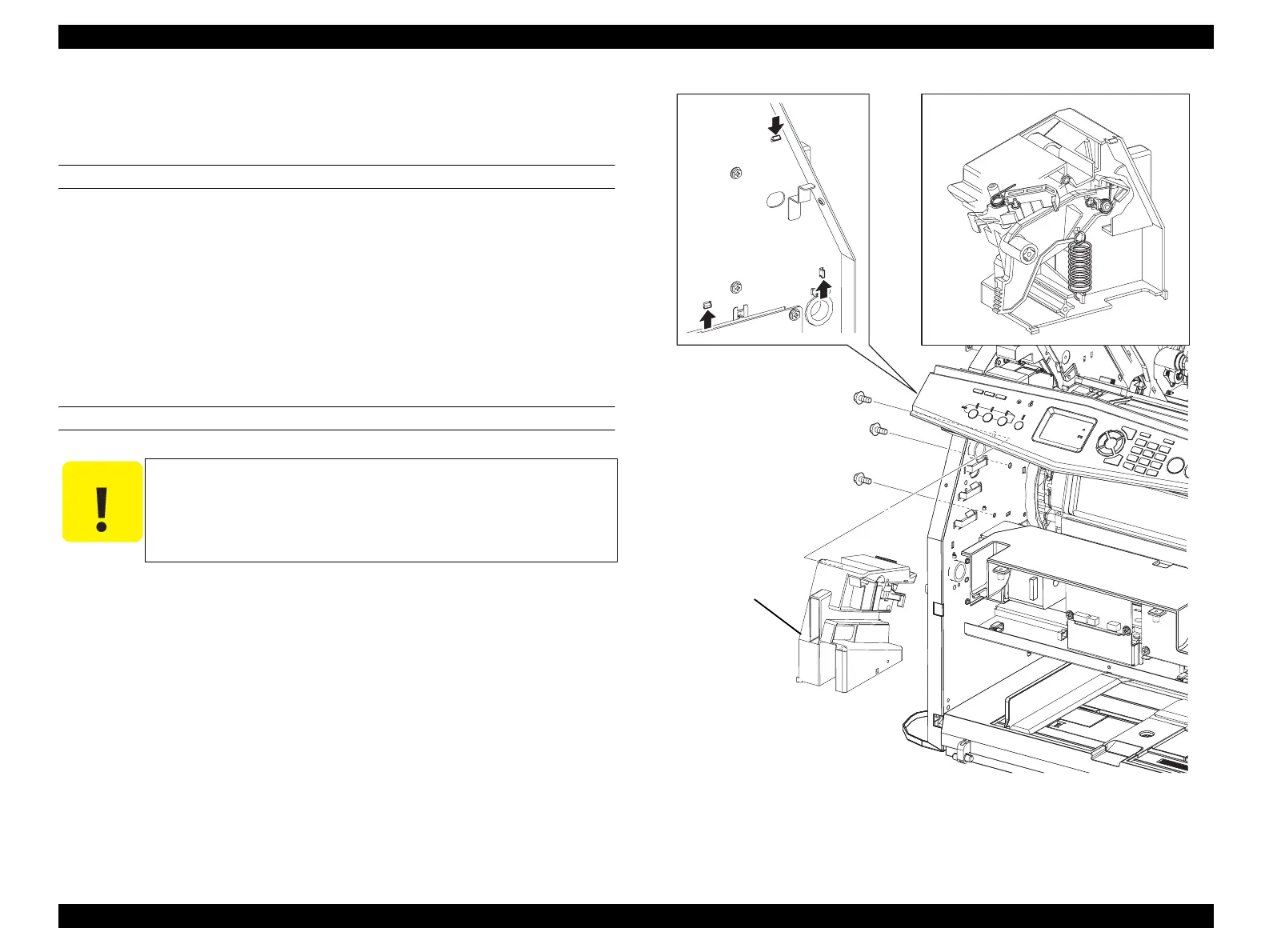
1. Remove COVER ASSY LH. (p321)
2. Remove LV/HVPS. (p435)
3. Remove the 3 screws (silver, with flange, tapping, 8 mm) fastening LATCH
ASSY-ROTARY to the main unit.
4. Unhook the three hooks fastening LATCH ASSY-ROTARY to the main unit, and
remove LATCH ASSY-ROTARY.
REINSTALLATION
1. Match the hook on LATCH ASSY-ROTARY with the attachment position, and
attach to the main unit.
2. Fasten LATCH ASSY-ROTARY to the main unit with the 3 screws (silver, with
flange, tapping, 8 mm).
3. Attach LV/HVPS. (p435)
4. Attach COVER ASSY LH. (p321)
Figure 4-89. Removal of LATCH ASSY-ROTARY
C A U T I O N
Pay attention to the levers and springs inside LATCH ASSY-
ROTARY as they easily come loose.
When a part on LATCH ASSY-ROTARY comes off, referring to
the assembly drawing, assemble the part, and attach LATCH
ASSY-ROTARY to the main unit.
Leg_Sec03_088RA
CAUTION
3)
3)
3)
4)-2
4)-1
manuals4you.commanuals4you.com
 Loading...


