EPSON AcuLaser CX11/CX11F Revision B
DISASSEMBLY AND ASSEMBLY Scanner Section 489
4.3.3.3 PCB ASSY
REMOVAL
1. Remove the Scanner. (p306)
2. Remove the ADF Unit. (p481)
3. Remove the IR COVER A ASSY. (p482)
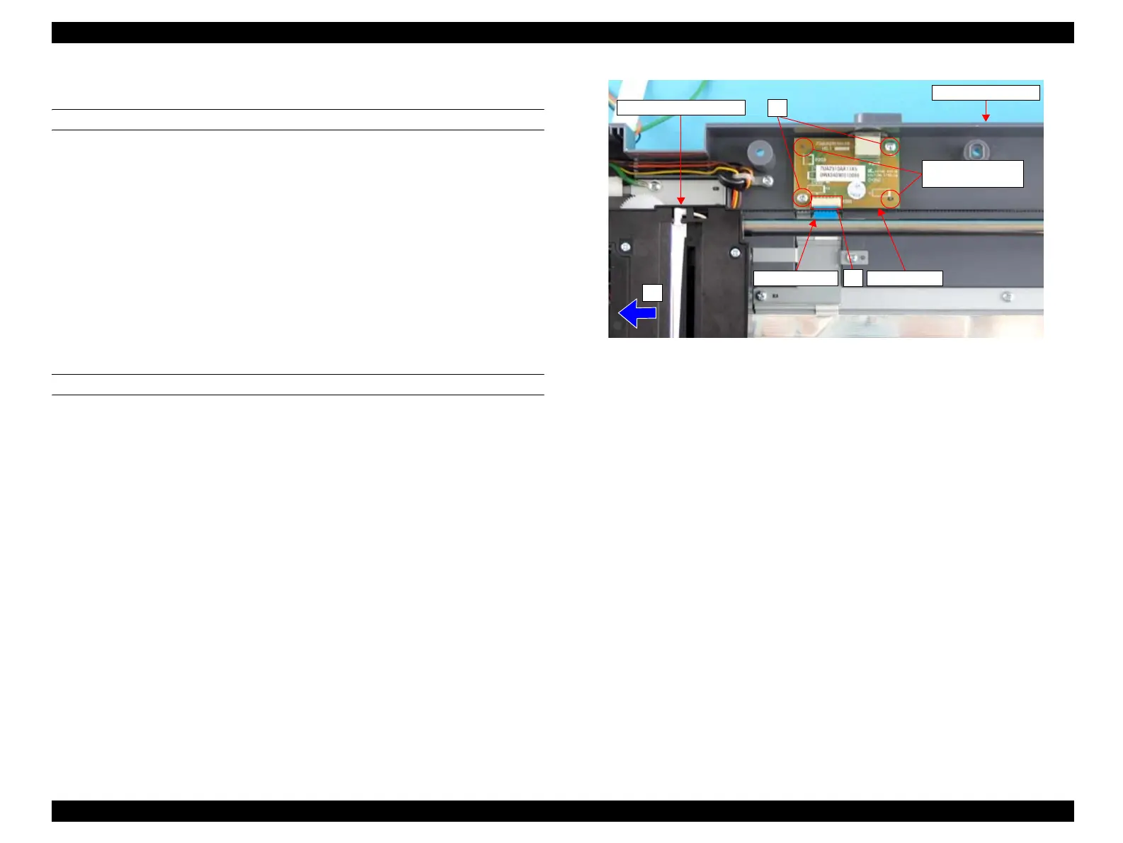
4. Move the CCD MODULE ASSY to the left side (home position side).
5. Disconnect the FFC BOARD from the connector on the PCB ASSY.
6. Remove the two screws (M3 x 8 mm, P-type, B-head) that secure the PCB ASSY
to the IR BASE A ASSY, and remove the PCB ASSY from the IR BASE A
ASSY.
REINSTALLATION
1. Match the positioning holes of the PCB ASSY and the guide pins of the IR BASE
A ASSY, and secure the PCB ASSY to the IR BASE A ASSY with the two screws
(M3 x 8 mm, P-type, B-head).
2. Connect the FFC BOARD to the P201 connector on the PCB ASSY.
3. Attach the IR COVER A ASSY. (p482)
4. Attach the ADF Unit. (p481)
5. Install the Scanner. (p306)
Figure 4-166. Removal of PCB ASSY
CCD MODULE ASSY
4)
6)
Positioning Holes
and Guide Pins
5)
IR BASE A ASSY
PCB ASSYFFC BOARD
 Loading...


