EPSON AcuLaser CX11/CX11F Revision B
DISASSEMBLY AND ASSEMBLY Scanner Section 488
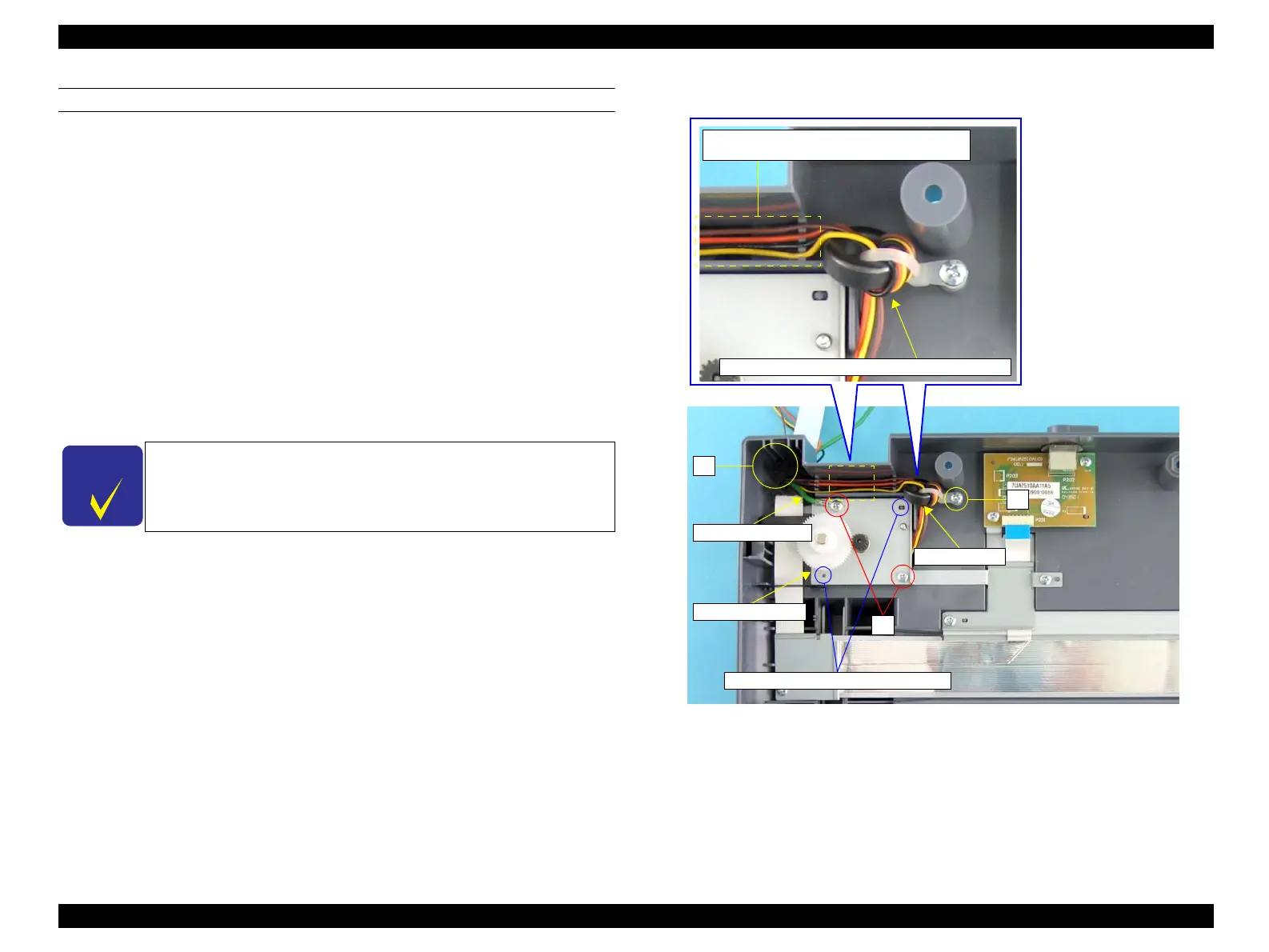
REINSTALLATION
1. Wind the harnesses of the MOTOR ASSY around the ferrite core once, and secure
them with the harness tie.
2. Draw the grounding wire through the hole of the IR BASE A ASSY.
3. Install the MOTOR ASSY to the IR BASE A ASSY matching the guide pins of
the IR BASE A ASSY with the positioning holes of the MOTOR ASSY.
4. Secure the bottom-right corner of the MOTOR ASSY with the screw (M3 x 8 mm,
P-type, B-head), and secure the upper-left corner of the assy. together with the
grounding terminal with the screw (M3 x 8 mm, P-type, B-head).
5. Secure the harness tie to the IR BASE A ASSY with the screw (M3 x 8 mm, P-
type, B-head).
6. Put the harnesses of the MOTOR ASSY through the hole of the IR BASE A
ASSY, and secure the harnesses on the groove of the IR BASE A ASSY.
7. Attach the CCD MODULE ASSY. (p485)
8. Attach the IR COVER A ASSY. (p482)
9. Attach the ADF Unit. (p481)
10. Install the Scanner. (p306)
Figure 4-165. Reinstallation of MOTOR ASSY
C H E C K
P O I N T
When securing the harnesses of the MOTOR ASSY on the groove of
the IR BASE A ASSY, arrange them in the prescribed order; brown,
orange, black, and yellow from the top as shown in
Figure 4-165
.
Place the harnesses in the order of brown,
orange, black, and yellow from the top.
Wind harnesses once around the ferrite core
Ferrite Core
5)
Grounding Wire
6)
MOTOR ASSY
4)
Positioning Holes and Guide Pins
manuals4you.commanuals4you.com
 Loading...