EPSON AcuLaser CX11/CX11F Revision B
DISASSEMBLY AND ASSEMBLY Printer 426
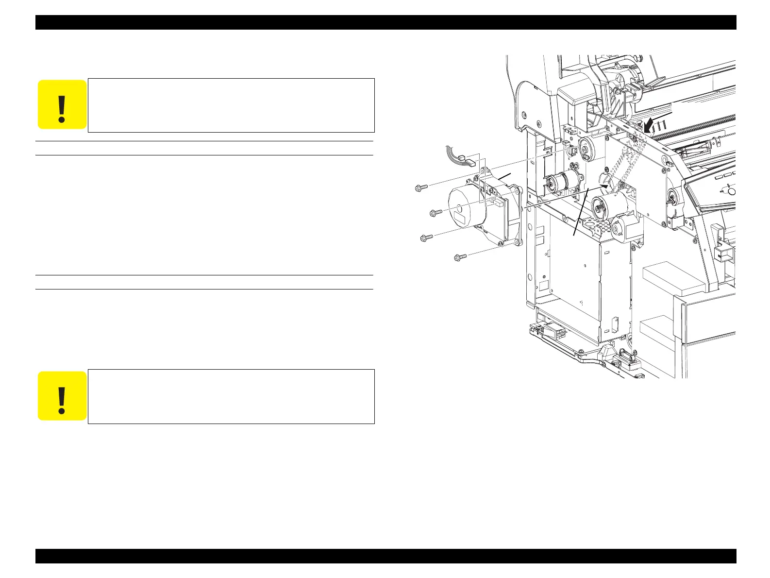
4.2.10.6 MOT ASSY P/R
REMOVAL
1. Remove COVER ASSY LH. (p321)
2. Disconnect connector (P/J200) and connector (P/J201) from MOT ASSY P/R.
3. Remove the 4 screws (silver, with flange, 10 mm) fastening MOT ASSY P/R to
the main unit.
4. Remove MOT ASSY P/R from the main unit.
REINSTALLATION
1. Attach MOT ASSY P/R to the main unit while lightly pressing LINK-
COUPLING.
2. Fasten MOT ASSY P/R to the main unit with the 4 screws (silver, with flange, 10
mm).
3. Attach connector (P/J200) and connector (P/J201) to MOT ASSY P/R.
4. Attach COVER ASSY LH. (p321)
Figure 4-108. Removal of MOT ASSY P/R
C A U T I O N
Step numbers with [ ] in the figure indicate the step of
reinstallation.
C A U T I O N
Lightly open/close COVER ASSY TOP, and check operation of the
coupling on MOT ASSY P/R.
Leg_Sec03_103RC
2)
3)
3)
3)
3)
4)
[1)-2]
[1)-1]
manuals4you.commanuals4you.com
 Loading...


