EPSON AcuLaser CX11/CX11F Revision B
APPENDIX Printer System Electrical Connection 576
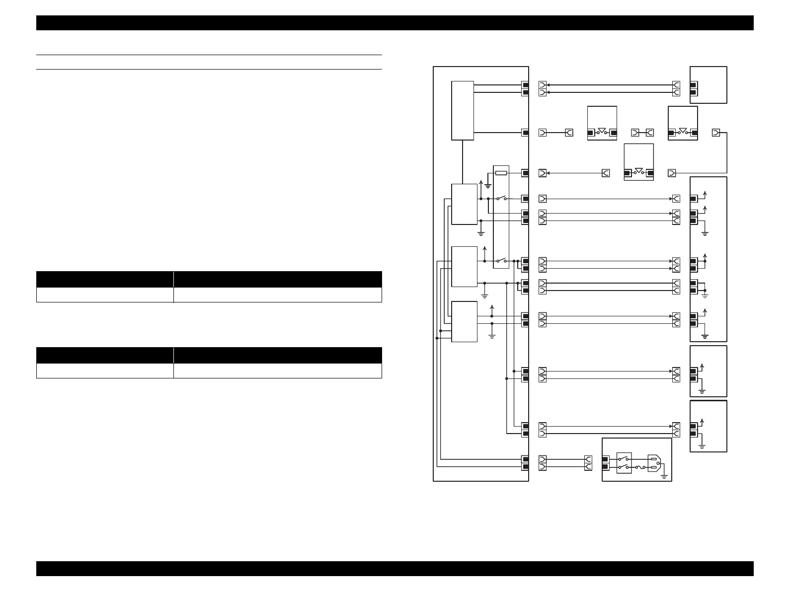
1. DC POWER SUPPLY
Overcurrent Protection
All outputs (+24VDC, +5VDC, +3.3VDC) from LV/HVPS are stopped when
short-circuiting on the way to the earth or ground. Each output is restored by
eliminating the cause of the short-circuit, and turning the printer OFF and then
back ON at specified time interval. The overcurrent protection circuit is activated
when a current exceeds 16A flows.
Overvoltage Protection
All outputs from LV/HVPS are stopped when an overvoltage is detected. The
operating voltages for overvoltage protection of each output are as follows:
+24VDC: 36VDC
+5VDC: 7VDC
+3.3VDC: 5VDC
Power save
Stopping output by Interlock Switch
The I/L +5VDC signal that arrives via Front Interlock Switch, Upper
Interlock Switch and Fuser Interlock Switch becomes the power source of the
LV/HVPS internal Relay coil. This signal opens/closes Relay contacts, and
controls INTERLOCK +24VDC and INTERLOCK +5VDC.
Figure 7-8. DC POWER SUPPLY Connection and Wiring Diagram
Name of Signal Line Remarks
POWER SAVE
Signal for turning +24VDC OFF
Name of Signal Line Remarks
I/L +5VDC
---
LV/HVPS
PL12.2.3
Power
Save
P/J500
3
+5VDC
Supply
+24VDC
Supply
+3.3VDC
Supply
15
P/J500
5
P/J502
3
4
+5VDC
+24VDC
5
6
7
8
1
2
9
10
11
12
+3.3VDC
PWBA MCU
PL12.2.1
4
P/J502
13
SWITCH-
INLK
FRONT
PL.1.1.27
SWITCH-
INLK
FUSER
PL.1.1.34
+5VDC
SWITCH
ASSY
TOP
PL.1.1.7
I/L +5VDC
POWER SAVE
P/J401
20
19
PWBA MCU
PL12.2.1
I/L +5VDC
P/J401
18
+5VDC
SG
P/J410
3
4
I/L +24VDC
I/L +24VDC
SG
SG
5
6
7
8
+3.3VDC
SG
I/L +24VDC
SG
I/L +24VDC
SG
1
2
P/J201
1
2
P/J432
1
3
MOT ASSY P/R
PL11.1.6
PWBA FUSER CONTROL
PL12.2.12
P/J2
3
1
P/J503
3
1
Interlock
+24VDC
PWB ASSY
ROT
PL12.1.10
Interlock
+24VDC
Interlock
+5VDC
+5VDC
INTERLOCK
+24VDC
+3.3VDC
13
P/J115
3
P/J115
1
3
P/J116
1
1
P/J116
3
3
P/J117
1
1
P/J117
3
Leg_Sec007_002FB
manuals4you.commanuals4you.com
 Loading...


